

1 引言
2 结果与讨论
2.1 材料结构与形貌分析


图2 LMO@1YSZ复合材料新鲜样品的透射电子显微镜照片. (a) TEM显示包覆层YSZ; (b) HR-TEM中YSZ四方相的铁弹畴、YSZ和LMO的晶格条纹Figure 2 TEM images of as-synthesized LMO@1YSZ composite. (a) TEM showing YSZ coating layer on LMO particle; (b) HR-TEM showing ferroelastic domains and lattice strips corresponding to YSZ and LMO crystallites |

2.2 电化学性能分析
2.2.1 充放电行为分析

图4 (a)纯LMO、LMO@1YSZ和LMO@3YSZ首次充放电曲线; (b)纯LMO、LMO@1YSZ和LMO@3YSZ第5周的充放电曲线; (c)纯LMO、LMO@1YSZ和LMO@3YSZ达到最大放电容量时的充放电曲线Figure 4 (a) The initial charge and discharge curves of pure LMO, LMO@1YSZ and LMO@3YSZ; (b) Charge and discharge curves for the 5th cycle of pure LMO, LMO@1YSZ, and LMO@3YSZ; (c) Charge and discharge curves of pure LMO, LMO@1YSZ, and LMO@3YSZ at maximum discharge capacity |
表1 纯LMO、LMO@1YSZ和LMO@3YSZ电极首次充/放电比容量及其库伦效率Table 1 Initial charge-discharge capacity and Coulomb efficiency of pure LMO, LMO@1YSZ and LMO@3YSZ electrode |
| 电极名称 | 初始充电比容量/ (mAh•g−1) | 初始放电比容量/ (mAh•g−1) | 库伦效率 |
|---|---|---|---|
| LMO | 350.60 | 138.17 | 39.40% |
| LMO@1YSZ | 323.28 | 157.60 | 48.75% |
| LMO@3YSZ | 321.62 | 113.13 | 35.17% |

2.2.2 循环稳定性分析
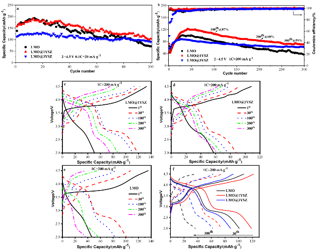
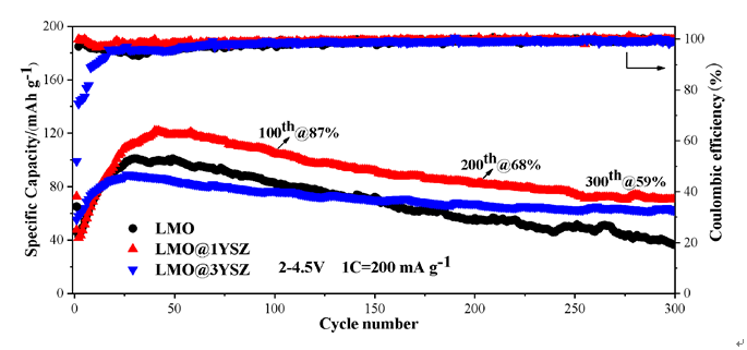
图6 合成材料LMO、LMO@1YSZ和LMO@3YSZ的电化学性能. (a), (b)分别为材料在0.1C和1C循环性能; (c)~(e)分别为材料在200 mA•g−1时不同循环周次的充放电曲线; (f)为相应的30周和第300周的充放电曲线Figure 6 Electrochemical properties of synthesized LMO, LMO@1YSZ, and LMO@3YSZ materials. (a), (b) Cycle performances at 0.1C and 1C; (c)~(e) charge-discharge curves at different cycles at 200 mA•g−1; (f) charge-discharge curves at 30th and 300th |
