


1 引言
2 结果与讨论
2.1 COFs合成与表征
2.1.1 材料结构与晶体学表征
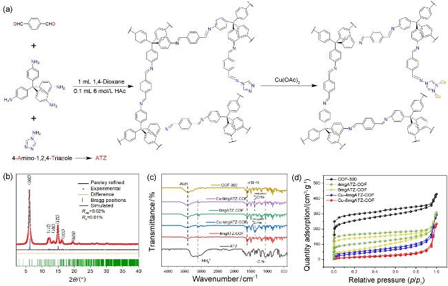
图1 (a) Cu-ATZ-COF合成过程的示意图; (b) COF-300的PXRD图谱, 包含实验图(黑色)、Pawley拟合图(黑色)、差值曲线(橙色)与衍射峰位置(绿色); (c)各样品的傅里叶变换红外光谱(FT-IR): 包括COF-300、4mgATZ-COF、8mgATZ-COF、Cu-4mgATZ-COF、Cu-8mgATZ-COF及ATZ单体; (d)各样品在77 K下的氮气吸附-脱附等温线图Figure 1 (a) schematic diagram of the synthesis of Cu-ATZ-COF. (b) PXRD patterns of COF-300. Observed (black), Pawley-refined (black), difference between observed and refined profiles (orange) and brag (green). (c) FT-IR spectra of COF-300, 4mgATZ-COF, 8mgATZ-COF, Cu-4mgATZ-COF, Cu-8mgATZ-COF and ATZ. (d) N2 adsorption-desorption isotherm of COF-300, 4mgATZ-COF, 8mgATZ-COF, Cu-4mgATZ-COF and Cu-8mgATZ-COF at 77 K |
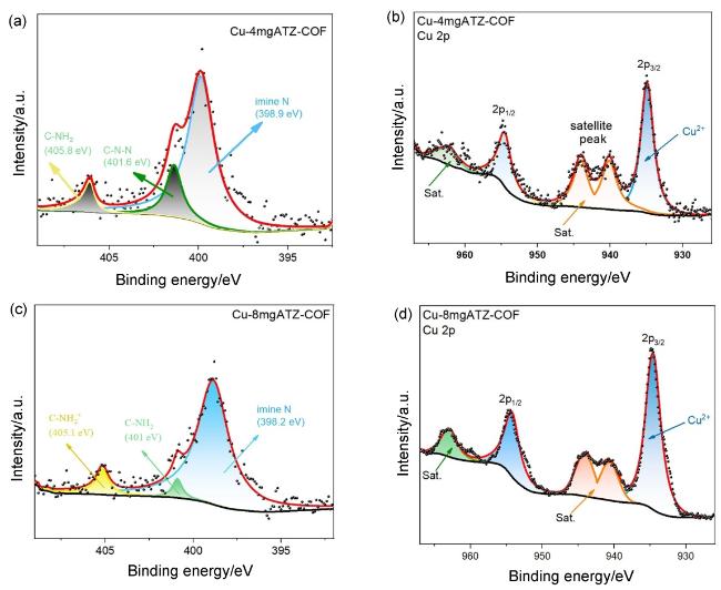
2.1.2 化学结构与孔结构分析
2.2 电催化性能评估

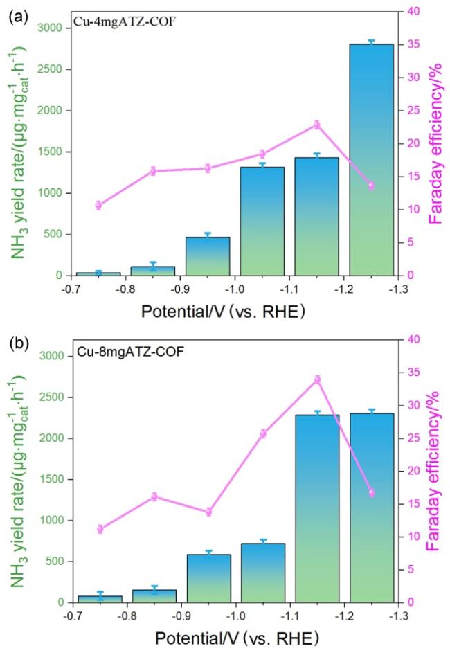
图3 (a)各催化剂在$N{\text{O}}_{3}^{-}$电解液中的线性扫描伏安曲线(LSV); (b)在-0.75 V至-1.25 V (vs. RHE)电位区间内, 不同催化剂的氨产率对比; (c)在相同电位范围内, 各催化剂的法拉第效率对比; (d) Cu-4mgATZ-COF和Cu-8mgATZ-COF的时间-电位稳定性测试曲线; (e)各样品的双电层电容(Cdl)测试结果; (f)各催化剂的电化学阻抗谱(EIS), 插图为拟合的等效电路模型Figure 3 (a) LSV curves of COF-300, 4mgATZ-COF, 8mg ATZ-COF, Cu-4mgATZ-COF and Cu-8mgATZ-COF. (b) The NH3 yield of all catalysts at -0.75 V to -1.25 V (vs. RHE). (c) The FE distribution comparison of all catalysts at -0.75 V to -1.25 V (vs. RHE). (d) Time-dependent potential curves for Cu-4mgATZ-COF and Cu-8mgATZ-COF. (e) Double-layer capacitance (Cdl) measurements of COF-300, 4mgATZ-COF, 8mgATZ-COF, Cu-4mgATZ-COF and Cu-8mgATZ-COF. (f) The impedance for COF-300, 4mgATZ-COF, 8mgATZ-COF, Cu-4mgATZ-COF and Cu-8mgATZ-COF. Inset: the equivalent electric circuit |