

1 引言
2 透明光伏技术
2.1 透明光伏技术特征
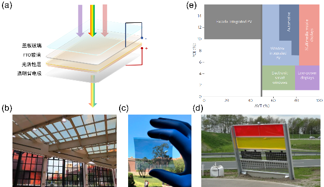
图1 (a)透明光伏的器件结构示意图; (b)基于碲化镉薄膜太阳能发电技术的透明光伏采光顶, 中国西部科技创新港7号楼[9]; (c)柔性透明有机光伏器件[11]; (d)基于发光太阳能聚光器型的透明光伏在隔音屏障中的使用[12]; (e)透明光伏各领域应用的PCE及AVT要求[13]Figure 1 (a) Structure of transparent photovoltaic; (b) Skylight roof with CdTe power generation glass, Building 7, Science and Technology Innovation Harbour, Western China[9]; (c) Organic photovoltaic products[11]; (d) Sound barrier prototype based on LSC-TPV[12]; (e) PCE and AVT requirements for transparent photovoltaic applications in different areas[13] |
表1 不同透明光伏技术的效率对比Table 1 An overview of TPV device based on different technologies |
| TPV | Active area/cm2 | AVT/% | PCE/% | LUE/% | Ref. |
|---|---|---|---|---|---|
| c-Si | 36 | 20 | 12.2 | 2.44 | [10] |
| a-Si | 0.25 | 29.3 | 6.41 | 1.88 | [14] |
| CIGS | 0.25 | 18.6 | 6.46 | 1.20 | [15] |
| CIGS | — | 12.3 | 10.5 | 1.29 | [16] |
| CdTe | — | 43 | 0.41 | 0.18 | [17] |
| OPV | 1.05 | 38.7 | 12.95 | 5.00 | [18] |
| Perovskite | 0.1 | 22 | 14.21 | 3.13 | [19] |
| Dye-Sensitized Solar Cell | 14 | 26 | 8.7 | 2.26 | [20] |
| CuInS2/ZnS QDs-LSC | 81 | 54 | 3.56 | 1.24 | [21] |
| CuInS2/ZnS QDs-LSC | 841 | 51 | 1.36 | 0.42 | [21] |
2.2 透明光伏的技术指标及技术挑战
3 LSC技术
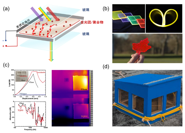
图2 (a) LSC-PV组件的结构示意图; (b) LSC器件在颜色[40]、柔性[41]和形状[42]方面的设计灵活性; (c) LSC器件与普通玻璃在机械强度及隔热、隔声性能方面的比较[43]; (d)基于LSC技术的发电窗户所建成的房屋模型[44]Figure 2 (a) Structure of luminescent solar concentrators; (b) Design freedom of luminescent solar concentrators with colour tunability[40], flexibility[41], and shape diversity[42]; (c) Mechanical properties and thermal and acoustic insulation of the LSC as a building material, compared with regular glass[43]; (d) Model house based on LSC-solar power windows[44] |
3.1 LSC的技术特点
3.2 LSC-PV组件效率分析
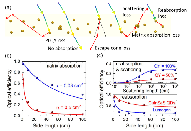
图3 (a) LSC器件内部光学损失过程分析; (b)对于具有不同吸收系数的波导介质, 正方形LSC器件光学效率随边长变化曲线[47]; (c)对于具有不同PLQY的发光团, LSC器件光学效率随散射系数变化的曲线(上)和对于具有不同重吸收系数的发光材料, 正方形LSC器件光学效率随边长变化曲线(下)[47]Figure 3 (a) Analysis of internal optical losses in the LSC device; (b) Optical efficiency versus side length of square LSC devices for waveguide media with different absorption coefficients[47]; (c) Optical efficiency versus scattering length for LSC devices with luminophores of different PLQY (top) and Optical efficiency versus side length of square LSC devices for luminophores with different reabsorption coefficients (bottom)[47] |
3.3 发光材料设计策略
3.3.1 发光材料PLQY
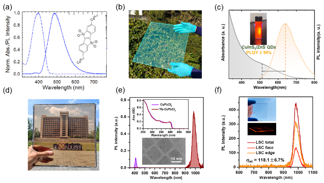
图4 (a)蓝色荧光染料C8-BTBT-Ox2-C8的分子结构式和UV-Vis吸收光谱-荧光光谱图以及(b)基于此染料的LSC大面积器件[53]; (c) CuInS2/ZnS量子点的UV-Vis吸收光谱-荧光光谱图和(d)基于此量子点的大面积LSC器件[21]; (e)未掺杂(紫色)和Yb-掺杂(深红色)CsPbCl3纳米晶体的荧光光谱以及相应的吸收光谱图(内嵌); (f)基于Yb-掺杂CsPbCl3纳米晶体的LSC器件(5 cm×5 cm)从总体(深红)、表面(浅红)和边缘(橙色)测试的荧光强度[55]Figure 4 (a) Molecular structure and UV-Vis absorption-photoluminescence (PL) spectra of blue fluorescent dye C8-BTBT-Ox2-C8, and (b) Large-area LSC device based on this dye[53]; (c) UV-Vis absorption-PL spectra of CuInS2/ZnS quantum dots, and (d) Large-area LSC device based on these quantum dots[21]; (e) PL spectra of undoped (purple) and Yb-doped (dark red) CsPbCl3 nanocrystals with corresponding absorption spectra shown in the inset; (f) total (dark red), face (light red), and edge (orange) emissions measured for a 5 cm×5 cm QC-LSC using Yb3+-doped CsPbCl3 NCs[55] |
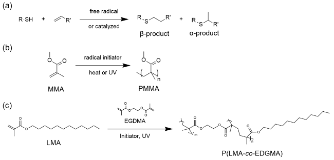
图5 (a)由巯基和烯基通过迈克加成反应进行聚合的聚硫醚反应式; (b) MMA结构式及由MMA聚合成为PMMA的反应式; (c) LMA结构式及由LMA聚合成为PLMA的反应式, 其中EGDMA可作为聚合体系中的交联剂Figure 5 (a) Reaction scheme for thiol-ene polymerization via Michael addition between thiol and ene groups; (b) Chemical structure of MMA and its polymerization to PMMA; (c) Chemical structure of LMA and its polymerization to PLMA with EGDMA as crosslinker in the system |
3.3.2 LSC波导效率
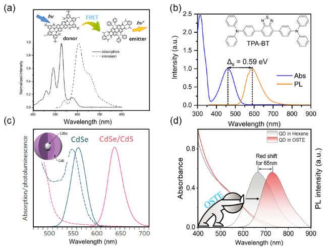
图6 (a)优化后供体-受体有机染料对在PMMA中的吸收和荧光光谱[65]; (b)具有聚集诱导发光效应的染料TPA-BT的吸收光谱和荧光光谱[41]; (c)通过厚壳策略增大Stokes shift的CdSe/CdS量子点的吸收光谱和荧光光谱[66]; (d)嵌入OSTE基质后CuInS2/ZnS量子点的荧光光谱红移65 nm, 使量子点的光谱重叠系数显著降低[21]Figure 6 (a) Absorption and emission spectra for the optimized blend of the donor-emitter mixture in PMMA[65]; (b) Absorption and photoluminescence spectra of TPA-BT[41]; (c) Absorption and PL spectra of CdSe/CdS QDs with enlarged Stokes shift achieved via thick-shell design[66]; (d) Significant 65-nm red shift in PL spectra of CuInS2/ZnS QDs embedded in OSTE polymer matrix, resulting in dramatically reduced spectral overlap integral[21] |
3.4 LSC-PV应用前景展望
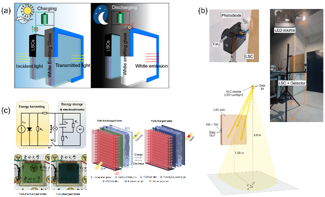
图7 LSC技术联用示意图. (a)由LSC和白光LED构成的双层玻璃在日间(左边)和夜晚(右边)状态的设计示意图[71]; (b)由LSC作为VLC光学接收器的示意图[72]; (c) LSC-ECS联合器件的结构以及充-放电示意图[73]Figure 7 Schematic diagram of LSC technology integrated with auxiliary technologies. (a) Schematic design of a double window made of LSC and white light-emitting glass for daytime (left) and nighttime (right)[71]; (b) Schematic of LSC as a VLC receiver in light[72]; (c) Structure and charging/discharging diagram of LSC-ECS[73] |