




1 引言
2 捕集-催化双功能MOF: 从材料内协同到器件级解耦的递进式设计
2.1 孔道内原位协同: 氨基功能化Ag-MOF直接还原烟气CO2制CO
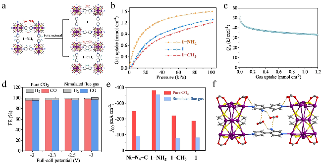
图1 (a) 1, 1-CH3和1-NH2的合成路线及制备示意图. (b) 在298 K下测得的1, 1-CH3和1-NH2的CO2吸附脱附等温线. (c) 1-NH2的CO2吸附焓. (d) 1-NH2在CO2气氛和模拟烟气中对CO的选择性. (e) 1-NH2在CO2气氛和模拟烟气中对CO的部分电流密度. (f) 1-NH2对CO2和 H2O分子的吸附活性位点Figure 1 (a) Preparation route and structures of 1, 1-CH3, and 1-NH2. (b) CO2 adsorption and desorption isotherms measured at 298 K for 1, 1-CH3, and 1-NH2. (c) CO2 adsorption enthalpy for 1-NH2. (d) Comparison of CO selectivity for 1-NH2 measured in CO2 atmosphere and simulated flue gas. (e) Partial current density of CO for 1-NH2 under pure CO2 atmosphere and simulated flue gas. (f) The adsorption active sites for CO2 and H2O molecules of 1-NH2 |
2.2 捕集-催化一体化制液体产物: 导电Bi-MOF在烟气条件下高效生成甲酸
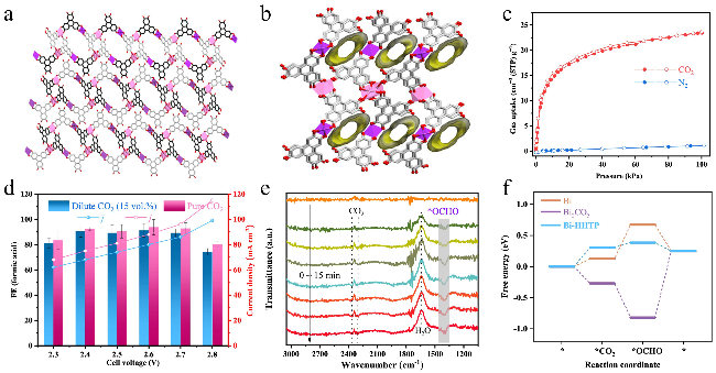
图2 (a) Bi-HHTP的一维锯齿形双链结构. (b) Bi-HHTP的三维π-π堆积结构, 沿b轴方向具有一维孔道. (c)在298 K下的CO2和N2吸附脱附等温线. (d)在高纯CO2和稀释CO2气氛下, 不同电池电压对应的FE(HCOOH)和电流密度. (e) Bi-HHTP上随时间变化的eCO2RR的原位衰减全反射傅里叶变换红外光谱. (f) Bi、Bi2CO5和Bi-HHTP上eCO2RR的吉布斯自由能变Figure 2 (a) 1D zigzag double chains of Bi-HHTP. (b) 3D π-π stacking structure of Bi-HHTP with 1D pores along the b-axis direction. (c) CO2 and N2 sorption isotherms measured at 298 K. (d) FE(HCOOH) values and current densities under different cell voltages in high-purity CO2 and dilute CO2 (V(CO2)∶V(N2)=15∶85) atmospheres, respectively. (e) Time-dependent operando ATR-FTIR spectra for the eCO2RR on Bi-HHTP. (f) Calculated Gibbs free energy evolution of eCO2RR on Bi, Bi2CO5, and Bi-HHTP, respectively |
2.3 反应环境协同调控: 酸性条件下质子化MOF实现高碳效率制甲酸
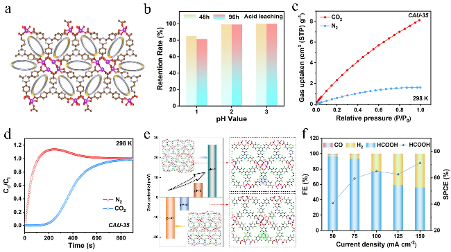
图3 (a) CAU-35的结构示意图. (b)不同酸浸条件下Bi活性位点的保留率. (c) CAU-35在298 K下的CO2和N2吸附脱附等温线. (d) 298 K、0.1 MPa条件下, CO2/N2 (V(CO2)∶V(N2)=15∶85)混合气体在CAU-35上的穿透曲线(Ci和Co分别为气体在进口和出口处的浓度). (e) 298 K下CAU-35在不同pH值下的ζ电位(溶剂为去离子水, pH值通过盐酸调节以避免离子干扰). (f) pH=2、稀释CO2流速为6 mL/min时, CAU-35在不同总电流密度下的单通转化效率(SPCE)和法拉第效率(FE)Figure 3 (a) Structure of CAU-35. (b) Retention rate of Bi sites after acid leaching under different conditions. (c) CO2 and N2 sorption isotherms of CAU-35 measured at 298 K. (d) Breakthrough curves for a 15∶85 (V/V) mixture of CO2/N2 at 298 K and 0.1 MPa. Ci and Co are the concentrations of each gas at the inlet and outlet, respectively. (e) ζ-Potential of CAU-35 at different pH values at 298 K. The solvent is DI water, and pH is adjusted with HCl to avoid ion interference effects. (f) SPCE and FE on CAU-35 at different total current densities with a dilute CO2 flow rate of 6 mL/min at pH=2 |
2.4 器件级功能解耦: MOF基分子筛膜实现低浓度CO2的原位纯化与转化
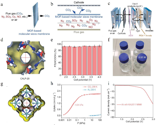


图5 (a, b) MOF基分子筛分膜提纯CO2示意图. (c)装有MOF基分子筛分膜的MEA-SSE电解池示意图. (d) CALF-20的孔结构. (e)以烟气为原料、嵌入CALF-20-MMM时, 不同电解池电压下的FE(HCOOH). (f) 300 h连续电解后得到的1.8 L甲酸水溶液(浓度0.91 mol•L−1). (g) KAUST-7的孔结构. (h) 298 K下KAUST-7的CO2与N2吸附等温线. (i)以Bi纳米颗粒为催化剂、空气为原料, 在嵌入KAUST-7-MMM的流动电池中测试得到的LSV曲线Figure 5 (a, b) Schematic diagram of the membrane separation device. (c) MEA-SSE electrolyzer embedded with MOF-based MMM. (d) Pore structure of CALF-20. (e) FE(HCOOH) values under different cell voltages with dilute CO2 as feedstock embedded with CALF-20-MMM. (f) 1.8 L of HCOOH aqueous solution (0.91 mol•L−1) after 300 h continuous electrolysis. (g) Pore structure of KAUST-7. (h) CO2 and N2 adsorption isotherms of KAUST-7 at 298 K. (i) LSV curve by Bi NPs as catalyst with air as feedstock in flow cell embedded with KAUST-7-MMM |