


1 引言
表1 二氧化碳加氢生成C2+产物的代表性催化剂及其催化性能结果Table 1 Representative catalysts and their catalytic performance for hydrogenation of CO2 to C2+ species. |
| Entry | Catalysts | CO2 Conversion/% | CO Selectivity/% | Hydrocarbon distributiona/% | GHSV/ (mL•g-1•h-1) | Temperature./℃ | Pressure/ MPa | Ref. | |||
|---|---|---|---|---|---|---|---|---|---|---|---|
| CH4 | C20~C40 | C2=~C4= | C5+ | ||||||||
| 1 | Co-Fe | 31.4 | — | 20.4 | 57.3 | 22.3 | 9600 | 320 | 1 | [12] | |
| 2 | Na/Fe@CoCo-3 | 50.3 | 4.6 | 13.9 | 41.3 | 44.8 | — | 330 | 3 | [13] | |
| 3 | Fe-Co(0.17)/K(1.0) | 31.0 | 18.0 | 15.9 | 84.1 | 3600 | 300 | 1.1 | [14] | ||
| 4 | Ni/Fe=1:99 | 32.6 | 89.1 | 57.0 | 7.4 | 35.6 | 0 | 5000 | 350 | — | [15] |
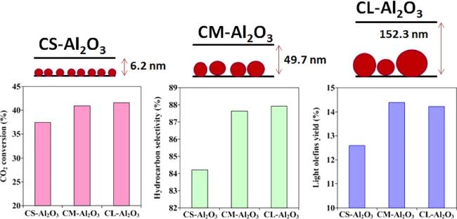
| 5 | CM-Al2O3 | 41.0 | 12.4 | 33.7 | 6.4 | 41.1 | 18.7 | — | 320 | 2 | [20] |
| 6 | Fe/CeO2 rods | 20.6 | 61.2 | 80.6 | 6.2 | 12.3 | 0.6 | 1600 | 390 | — | [21] |
| 7 | Fe(12.9) | 12.8 | 49.5 | 67.7 | 28.5 | 1.4 | 2.4 | 18000 | 320 | 3 | [22] |
| 8 | Fe/ZrO2 | 42 | 15 | 20.0 | 8.2 | 46.0 | 26.8 | 1200 | 340 | 2 | [23] |
| 9 | N-600-0 | 46 | 17.5 | 32.2 | 17.6 | 23.3 | 26.9 | 3600 | 400 | 3 | [26] |
| 10 | Fe/C-K@NC-350/500 | 35.1 | 28.1 | 23.8 | 7.9 | 37.7 | 30.6 | 5000 | 340 | 3 | [28] |
| 11 | 40FeK/SMC | 44.7 | 85.5 | 4.8 | 6.5 | 13.6 | 75.1 | — | 260 | 2 | [34] |
| 12 | Fe-K/HPCMs1 | 33.4 | 38.9 | 22.1 | 18.8 | 29.5 | 29.6 | 3600 | 400 | 3 | [35] |
| 13 | IO@gC-1.0 | 21.9 | 78.3 | 50.5 | 46.3 | 3.2 | — | 370 | — | [36] | |
| 14 | FeNa/EG-A | 42.4 | 8.3 | 12.6 | 7.8 | 38.0 | 41.6 | 2000 | 320 | 3 | [37] |
| 15 | Fe-Cu-K/ZSM-5(Si/Al=25) | 37.7 | 80.7 | 18.3 | 24.9 | 56.8 | 2000 | 300 | 1 | [41] | |
| 16 | Mn15Na32im | 31.9 | 97.2 | 12.4 | 6.2 | 33.0 | 48.4 | 11000 | 320 | 1.5 | [47] |
| 17 | IWI200 | 22.4 | 17.8 | 46.3 | 33.0 | 7.8 | 12.9 | 36000 | 300 | — | [49] |
| 18 | 3% (w) Rb/Fe3O4 | 39.7 | 8.1 | 19.5 | 4.4 | 47.4 | 28.7 | 2500 | 300 | 0.5 | [50] |
| 19 | FeMnZr4K | 39.0 | 81.5 | 15.4 | 4.7 | 28.4 | 51.5 | 12000 | 320 | 1 | [51] |
| 20 | 1Fe-1Zn-K | 51.0 | 6.0 | 34.9 | 7.8 | 53.6 | 3.7 | 1000 | 300 | 0.5 | [55] |
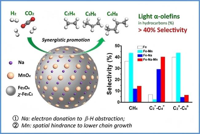
| 21 | 5Mn-Na/Fe | 38.6 | 11.7 | 13.5 | 4.6 | 34.6 | 47.2 | 2040 | 320 | 3 | [57] |
| 22 | 0.14Mn/Fe3O4-NaAc | 27.0 | 26.8 | 14.4 | 6.4 | 40.3 | 38.9 | — | 320 | 0.5 | [58] |
| 23 | FeMnNd | 49.3 | 74.9 | 20.2 | 9.1 | 36.0 | 34.3 | 4000 | 300 | 1 | [62] |
| 24 | 20Fe0.5Cu0.5Nd/MOR | 23.3 | 28.3 | 34.9 | 27.1 | 25.4 | 12.6 | — | 350 | 1 | [63] |
| 25 | 35Fe-7Zr-1Ce-K | 57.34 | 3.05 | 20.64 | 7.86 | 55.62 | 15.87 | 1000 | 320 | 2 | [64] |
| 26 | Fe@C-1.0 | 52.3 | 92.6 | 8.5 | 4.2 | 26.0 | 61.3 | 3000 | 300 | 2 | [67] |
a The hydrocarbon distribution was calculated without CO. |
2 Fe基催化剂
2.1 双金属活性组分
2.2 载体
2.2.1 氧化物
2.2.2 金属有机框架材料
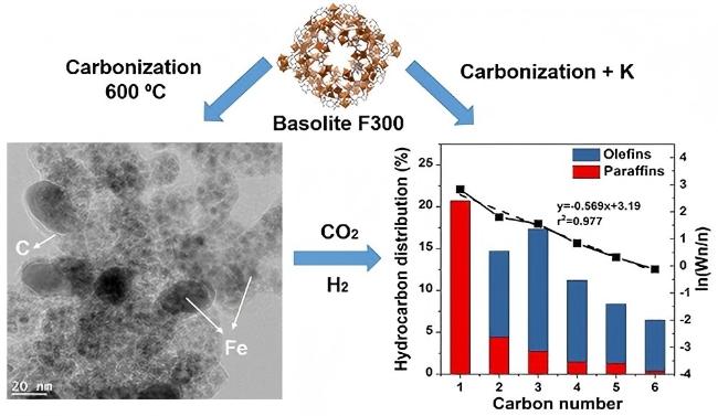
2.2.3 碳材料
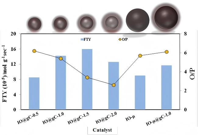
图5 二氧化碳加氢反应中IO@gC-0.5、IO@gC-1、IO@gC-1.5、IO@gC-2.0、IO-μ及IO-μ@gC-1.0催化剂的催化活性对比: 时空产率FTY与烯烷比O/P分析[36](反应条件: n(H2)∶n(CO2)=2∶1, 总流量为6 mL•min-1, 反应温度为370 ℃, 反应时间为12 h)Figure 5 Catalytic activity of IO@gC-0.5, IO@gC-1, IO@gC-1.5, IO@gC-2.0, IO-µ and IO-µ@gC-1.0 in hydrogenation of CO2 showing FTY and O/P ratio[36]. Reaction conditions: n(H2)∶n(CO2)=2∶1, with 6 mL•min-1 total flow rate at 370 ℃ at atmospheric pressure for 12 h |
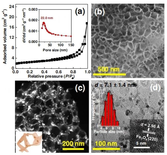
图6 (a) N2物理吸附等温线和孔径分布, (b)扫描电子显微镜(SEM)图像, (c)高角度环形暗场扫描透射电子显微镜(HAADF-STEM)图像, (d)透射电子显微镜(TEM)图像和制备的FeK1.5/HSG催化剂的颗粒分布图, (d)插图显示了催化剂上纳米粒子的晶格条纹[38]Figure 6 (a) N2 physisorption isotherms and pore size distribution, (b) SEM image, (c) HAADF-STEM image, and (d) TEM image and particle distribution histogram of the as-prepared FeK1.5/HSG catalyst. Inset in (d) shows the lattice fringes of the nanoparticle on the catalyst[38] |
2.2.4 沸石分子筛
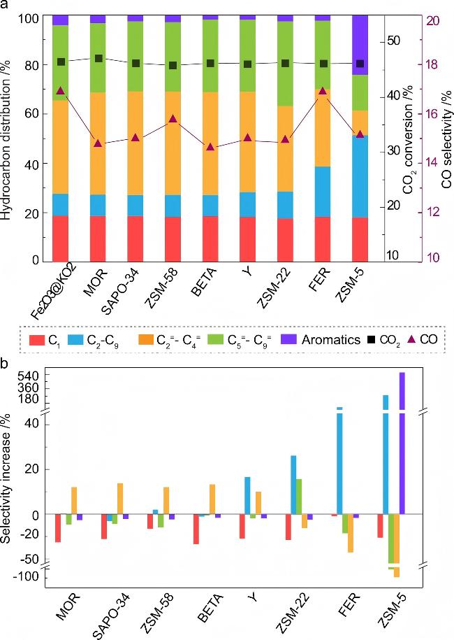
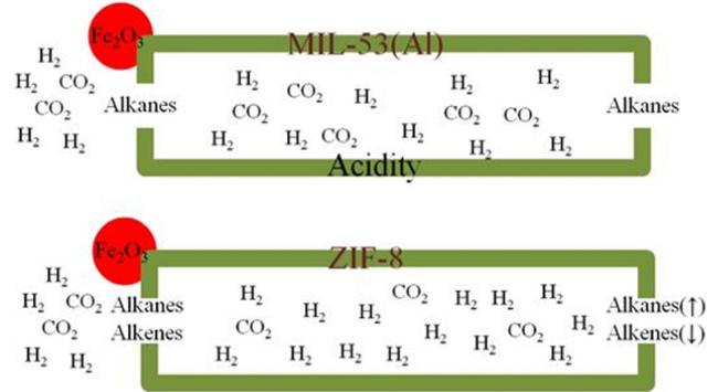
图7 Fe2O3@KO2/沸石双功能材料在CO2加氢过程中的催化性能[40]. (a)使用不同沸石的催化性能结果对比; (b)详细对比了与单独的Fe/K催化剂相比, 引入沸石分子筛后净选择性增加(或减少). 反应条件: 3 MPa、375 ℃、n(H2)∶n(CO2)=3∶1、10000 mL•g-1•h-1, 反应时间为48 h)Figure 7 Catalytic performance of the Fe2O3@KO2/zeolite bifunctional material catalyzed hydrogenation of CO2 process[40]. (a) Comparison of catalytic data using different zeolites; (b) Detailed illustration of the (net) selectivity increase (or decrease) of individual hydrocarbon groups upon introducing zeolites with respect to the standalone Fe/K catalyst. Reaction condition: 3 MPa, 375 ℃, n(H2)∶n(CO2)=3∶1, and 10,000 mL•g-1•h-1 at a time on stream of 48 h |
2.3 助剂
2.3.1 碱金属和碱土金属
2.3.2 过渡金属及其氧化物
2.3.3 稀土金属助剂
2.3.4 生物助剂
2.4 催化剂制备方法
3 双功能催化剂
4 Fe基催化剂的失活与活性相的识别
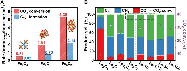
图11 二氧化碳加氢性能对比[84]. (A)不同催化剂的CO2转化率和C2+生成速率(反应条件: p=3 MPa, T=320 ℃, n(CO2)∶n(H2)=1∶3, TOS=20 min, 气体小时空速(GHSV)=72,000 mL•h-1•gcat-1); (B)不同反应时间(TOS)的模型催化剂(虚线左侧)与真实Fe(0)催化剂(虚线右侧)的产物选择性与CO2转化率对比(GHSV=18,000 mL•h-1•gcat-1, *GHSV=72,000 mL•h-1•gcat-1)Figure 11 Comparison of CO2 hydrogenation performance[84]. (A) CO2 conversion rate and C2+ formation rate over different model catalysts. Reaction conditions: p=3 MPa, T=320 ℃, n(CO2)∶n(H2)=1∶3, TOS=20 min, and GHSV=72,000 mL•h-1•gcat-1; (B) Product selectivity and CO2 conversion over model catalysts (on the left of the dashed line) and real Fe(0) catalysts with different TOS (on the right); GHSV=18,000 mL•h-1•gcat-1. *GHSV=72,000 mL•h-1•gcat-1 |
5 CO2加氢制低碳烯烃反应机理
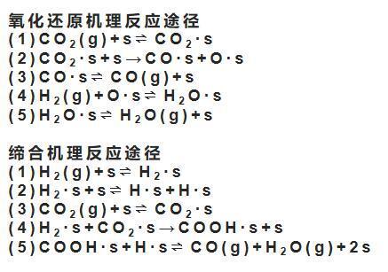
5.1 CO2-FTS途径机理
5.2 CO2-MeOH途径机理

图17 CO2通过CO2-MeOH转化为燃料和化学品[97]. (a)双功能催化剂上CO2加氢转化为C2+产物的反应机制示意图; (b)甲醇合成的两种可能反应途径; (c)通过碳氢化合物烃池机制在沸石内部将CH3OH转化为碳氢化合物的示意图Figure 17 CO2 hydrogenation to fuels and chemicals via the methanol reaction mechanism[97]. (a) Schematic for the reaction mechanism of direct CO2 hydrogenation to C2+ products over bifunctional catalysts; (b) Two possible reaction pathways for methanol synthesis; (c) Schematic for methanol conversion into hydrocarbons inside zeolites via the hydrocarbon-pool mechanism |