


1 引言
2 Al2O3的简介
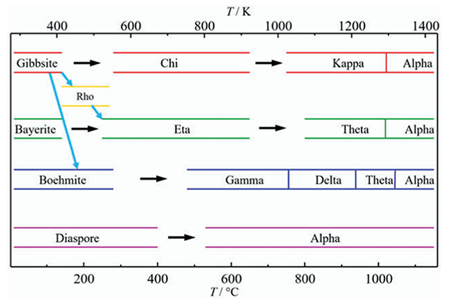
2.1 Al2O3的分类及晶格常数
| 氧化铝多晶型物 | 晶体结构 | 晶格常数 | |||||
|---|---|---|---|---|---|---|---|
| a/nm | b/nm | c/nm | α(º) | β(º) | Г(º) | ||
| α-Al2O3 | 三方 | 0.475 | 0.475 | 1.290 | 90 | 90 | 120 |
| γ-Al2O3 | 立方 | 0.792 | 0.792 | 0.792 | 90 | 90 | 90 |
| δ-Al2O3 | 四方 | 0.502 | 0.502 | 0.986 | 90 | 90 | 90 |
| θ-Al2O3 | 单斜 | 1.180 | 0.475 | 0.562 | 90 | 103 | 90 |
| ι-Al2O3 | 正交 | 0.773 | 0.761 | 0.292 | 90 | 90 | 90 |
| κ-Al2O3 | 正交 | 0.370 | 1.220 | 0.286 | 90 | 90 | 90 |
| σ-Al2O3 | 立方 | 0.794 | 0.794 | 0.794 | 90 | 90 | 90 |
2.2 非晶Al2O3

2.3 γ-Al2O3

2.4 α-Al2O3

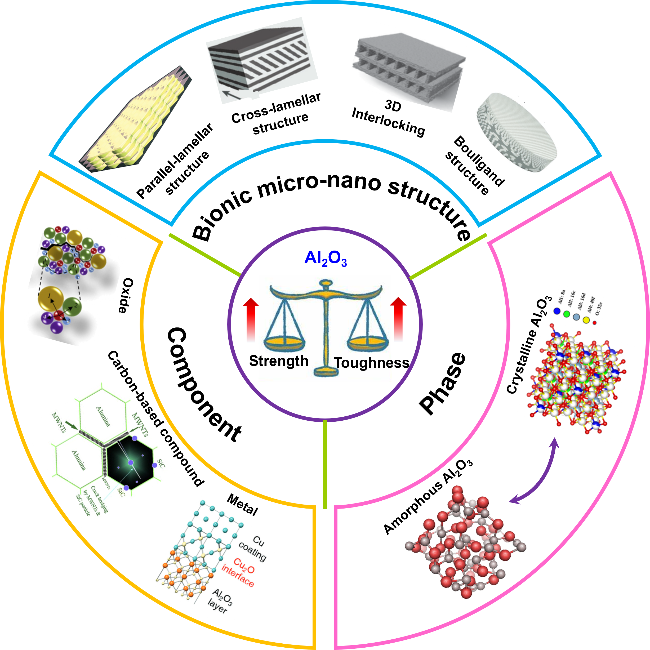
3 Al2O3及其复合材料的强韧化策略
3.1 物相调控
3.1.1 非晶化调控

图6 (a)拉伸应力与应变的关系. 插图I显示了弹性接触开始时(应变0.0)的独立拉伸样品的长度, 插图II显示了拉伸样品从底部断裂后的长度(比例尺, 500 nm); (b)剪切-压缩应力与应变的关系, 插图显示测试后变形的样品(比例尺, 100 nm)[58]Figure 6 (a) Tensile stress versus strain. Inset I shows the length of a stand-alone tensile sample at the beginning of elastic contact (strain 0.0), and Inset II shows the length of a tensile sample after it breaks from the bottom (scale bar, 500 nm); (b) shear-compression stress versus strain, and the inset shows the sample deformed after the test (scale bar, 100 nm)[58] |
3.1.2 晶体-非晶双相调控
3.2 组分调控
3.2.1 氧化物

图7 (a) Al2O3-ZrO2陶瓷的制备过程示意图; (b, c)Al2O3-ZrO2陶瓷裂纹扩展途径的扫描电镜照片; (d)不同固体负载烧结陶瓷的断裂韧性、弯曲强度和维氏硬度[72]Figure 7 (a) Schematic diagram of the preparation process of Al2O3-ZrO2 ceramics; (b, c) SEM photographs of crack propagation path of the Al2O3-ZrO2 ceramic; (d) fracture toughness, flexural strength and Vicker’s hardness of sintered ceramics with different solids loading[72] |
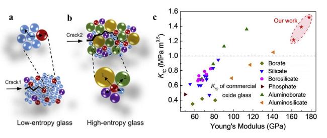
图8 (a, b)不同类型压痕裂纹在不同熵下的扩展及协调情况示意图, 裂纹1和裂纹2分别对应低熵和高熵; (c)合成的高熵玻璃以及一些商用氧化物玻璃和高断裂韧性氧化物玻璃的断裂韧性(KIC)与杨氏模量(E)的关系[33]Figure 8 (a, b) Diagram of different styles of indentation crack extends and coordination situation in different entropy, and the crack 1 and crack 2 are corresponded to low entropy and high entropy, respectively; (c) fracture toughness (KIC) versus Young’s modulus (E) for as-synthesized high-entropy glasses together with some commercial oxide glasses and high fracture toughness oxide glasses[33] |
3.2.2 碳及碳化物
3.2.3 金属
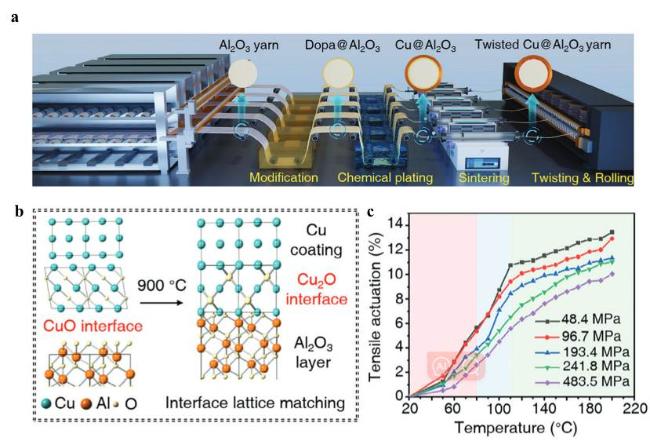
图9 (a) Cu@Al2O3丝的生产示意图; (b)使用界面晶格匹配策略形成稳定的Cu—O—Al键的示意图; (c)不同载荷下驱动应变与温度的关系曲线[35]Figure 9 (a) Schematic production of the Cu@Al2O3 filaments; (b) Illustration of forming stable Cu—O—Al bonds by using the interface lattice matching strategy; (c) the relationship curves between actuation strains and temperatures under different loads[35] |
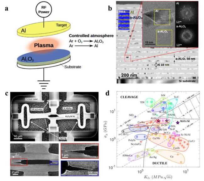
图10 (a, b) Al2O3/Al NLs的沉积及TEM表征; (c)通过裂纹测试测量Al2O3/Al NLs的断裂韧性; (d)单层和多层薄膜的屈服强度(σy)与断裂韧性(KIC)的函数关系图[83]Figure 10 (a, b) Deposition and TEM characterization of Al2O3/Al NLs; (c) measurement of fracture toughness of Al2O3/Al NLs by cracking test; (d) plot of yield strength (σy) as a function of fracture toughness (KIC) for monolayer and multilayer films[83] |
3.3 仿生启发的微纳结构设计
3.3.1 平行层结构

图11 (a) Al2O3/PMMA层状复合材料的制备示意图; (b) Al2O3/PMMA层状复合材料的SEM图; (c) Al2O3/PMMA层状复合材料烧结后的SEM图; (d) Al2O3/PMMA复合材料和天然珍珠层的弯曲应力-应变曲线; (e) Al2O3/PMMA复合材料、具有层状结构的材料和天然珍珠层的断裂韧性; (f, g) Al2O3/PMMA复合材料的增韧机制. 比例尺: 100 μm (b图和c图), 2 μm (f图和g图中插图), 10 μm (g图)[90]Figure 11 (a) Schematic diagram of synthesis of Al2O3/PMMA lamellar composites; (b) SEM image of Al2O3/PMMA lamellar composites; (c) SEM image of Al2O3/PMMA lamellar composites after sintering; (d) Flexural stress-strain curves of Al2O3/PMMA composites and natural pearl layers; (e) fracture toughness of Al2O3/PMMA composites, materials with lamellar structure and fracture toughness of natural pearl layers; (f, g) toughening mechanism of Al2O3/PMMA composites. Scale bar: 100 μm (Figures b and c), 2 μm (Figure f and the inset in (g), 10 μm (Figure g)[90] |

图12 (a)仿贝壳Al2O3复合陶瓷的制备过程示意图; (b)根据J积分和裂纹扩展Δa计算仿贝壳Al2O3陶瓷和珍珠层的断裂韧性; (c)仿贝壳Al2O3陶瓷的断裂面; (d)裂纹路径末端的多重裂纹和裂纹桥接. 箭头表示裂纹分支和桥接; (e)三种不同样品的弯曲强度; (f)在室温(25 ℃)和高温(600 ℃)下仿贝壳Al2O3陶瓷和标准氧化铝的裂纹起始韧性(KIC)和稳定裂纹扩展韧性(KJC)的比较[9]Figure 12 (a) Schematic diagram of the preparation process of nacre-inspired Al2O3 composite ceramics; (b) fracture toughness of nacre-inspired Al2O3 composite ceramics and nacre calculated from the J-integral and crack extension Δa; (c) fracture surface of the nacre-inspired Al2O3 composite ceramics; (d) multiple cracks at the end of the crack path and crack bridging. Arrows indicate the onset of crack branching and bridging; (e) flexural strengths of three different samples; (f) comparison of crack initiation toughness (KIC) and stable crack extension toughness (KJC) of nacre-inspired Al2O3 composite ceramics and a reference alumina at room temperature (25 ℃) and high temperature (600 ℃)[9] |
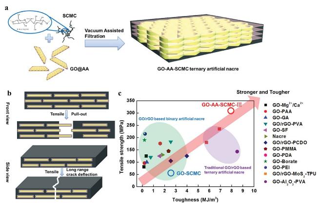
图13 (a) GO-AA-SCMC三元人工珍珠的合成工艺图; (b)三元人造珍珠质的断裂过程示意图(正视图和侧视图); (c) GO/rGO基二元人造珍珠层的拉伸强度和韧性[36]Figure 13 (a) Synthesis process of GO-AA-SCMC ternary artificial pearls; (b) sketch of the ternary artificial nacre’s fracture process (front and side view); (c) tensile strength and toughness for nacre, GO/rGO-based binary artificial nacre[36] |
3.3.2 交叉层结构
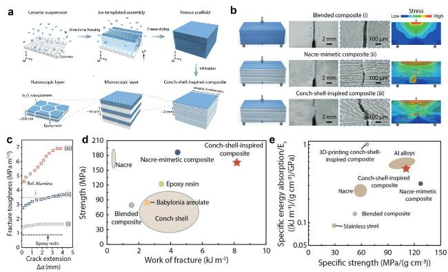
图14 (a)仿海螺壳复合材料的制造工艺和分层结构示意图; (b)三种复合材料的单边开口梁测试结果, 不同结构的示意图、裂纹扩展的光学图像、显示微观结构与裂纹挠度之间关系的扫描电镜图像以及有限元分析得出的断裂行为; (c)进行R曲线分析, 以确定与裂纹扩展(Δa)相关的断裂韧性(KJC). (d)大块仿生复合材料、天然珍珠层、海螺壳和环氧树脂的机械性能弯曲强度与断裂功的Ashby图; (e)大块仿生复合材料与珍珠岩和其他工程材料比强度与归一化比能量吸收的Ashby图[37]Figure 14 (a) Schematic illustration of the fabrication process and hierarchical architecture of the conch-shell-inspired composite; (b) the results of the single-edge notched beam tests of three composites. Schematic illustrations of different architectures, the optical images of crack propagation, SEM images indicating the relationship between the microstructure and the crack deflection, and the fracture behavior obtained from FEM. (c) R-curve analysis to characterize the fracture toughness (KJC) associated with the crack extension (Δa); (d) Ashby diagram of flexural strength versus work of fracture, demonstrating the mechanical properties of our bulk bioinspired composites, natural nacre, conch shell, and epoxy resin. (e) Ashby diagram of specific strength versus normalized specific energy absorption, comparing the bulk bioinspired composites with nacre and other engineering materials[37] |
3.3.3 三维互锁结构
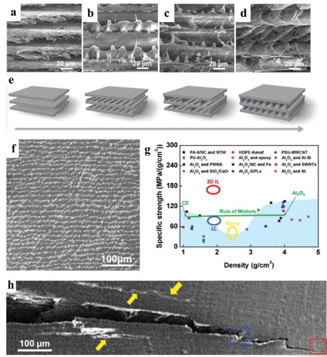
图15 (a~e) 3D IL骨架的形成过程示意图; (f)具有3D IL结构的Al2O3/CE复合材料SEM图; (g) Al2O3/CE复合材料与陶瓷/聚合物、陶瓷/金属、陶瓷/石墨烯、陶瓷/碳纳米管和典型聚合物基轻质复合材料的比强度和密度汇总图; (h)裂纹扩展的SEM图[38]Figure 15 (a~e) Schematic diagram of the formation process of the 3D IL skeleton; (f) SEM image of Al2O3/CE composite with 3D IL structure; (g) a summary of specific strength and density including Al2O3/CE composite, ceramic/polymer, ceramic/metal, ceramic/graphene, ceramic/carbon nanotube, and typical polymer-based lightweight composites; (h) SEM image of crack propagation[38] |
3.3.4 布利冈结构
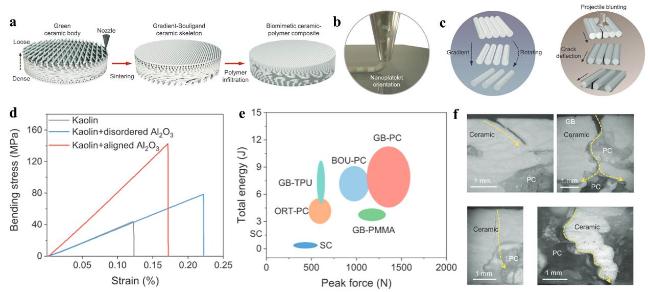
图16 (a)仿生GB复合材料的制备过程示意图; (b)示意图显示了在细丝挤出过程中由剪切力诱导的Al2O3纳米片的排列; (c)显示梯度和螺旋特征的GB陶瓷骨架示意图和相应的复合材料显示在冲击载荷下扭曲裂纹扩展; (d)高岭土陶瓷和含有无序排列Al2O3纳米片的高岭土-Al2O3 [40% (w)]陶瓷的典型弯曲应力-应变曲线; (e)高岭土-氧化铝基复合材料[40% (w)]与各种结构和聚合物的抗冲击性能比较; (f)仿生GB复合材料样品穿刺后详细裂纹路径的横截面观察[39]Figure 16 (a) Schematic illustration of the manufacturing process of the biomimetic GB composites; (b) schematic illustration showing the alignment of alumina nanoplatelets induced by shear force during the filament extrusion process; (c) schematic of GB ceramic skeleton showing gradient and helical features and corresponding composite showing twisted crack extension under impact loading; (d) typical bending stress-strain curves of kaolin ceramic and kaolin-alumina [40% (w)] ceramics with disordered and aligned alumina nanoplatelets; (e) comparison of impact resistance of the kaolin-alumina [40% (w)] based composites with various structures and polymers; (f) cross sectional observation of detailed crack paths in the biomimetic GB composite samples after puncture by optical microscope[39] |