


1 引言
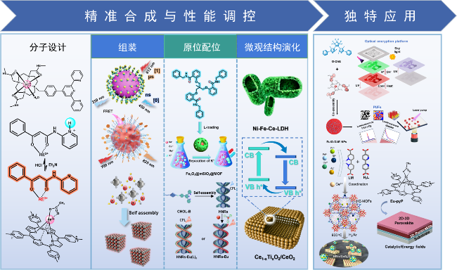
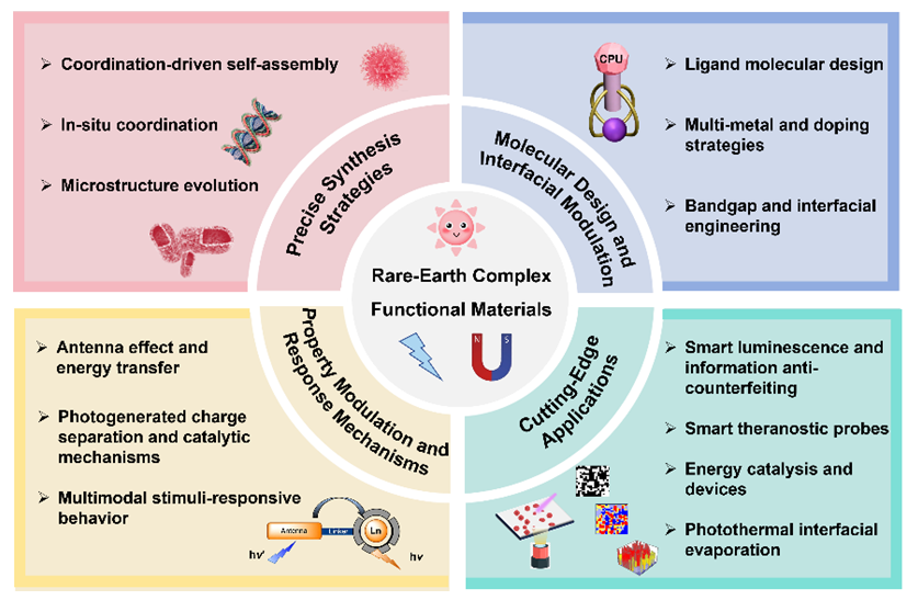
图1 稀土配合物功能材料的精准合成与分子/原子级性能调控及其在智能发光材料和光转换材料及器件领域应用的示意图Figure 1 Schematic representation of precision synthesis and molecular/atomic-scale property modulation of rare-earth complex functional materials, and their applications in smart luminescent materials and light-conversion materials and devices |
2 稀土配合物功能材料的精准合成与性能调控
2.1 配位自组装
2.1.1 稀土配合物的自组装
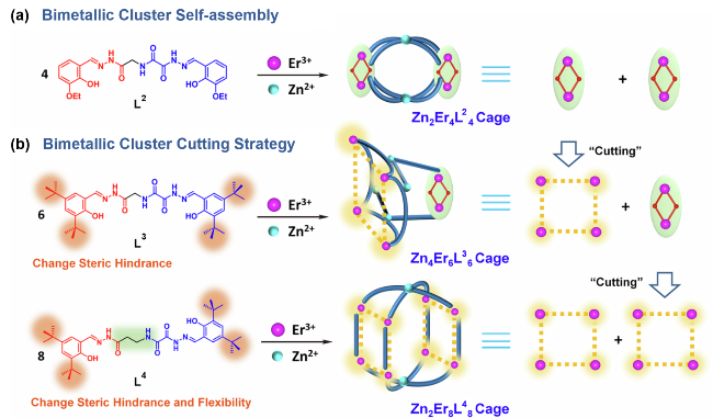
图3 构筑策略及自组装过程示意图: (a) Zn2Er4L24 超分子笼的构筑策略及自组装过程示意图; (b) Zn4Er6L36 和 Zn2Er8L48 超分子笼的构筑策略及自组装过程示意图Figure 3 Schematic illustration of the construction strategies and self-assembly processes for (a) the Zn2Er4L24 supramolecular cage; and (b) the Zn4Er6L36 and Zn2Er8L48 supramolecular cages |
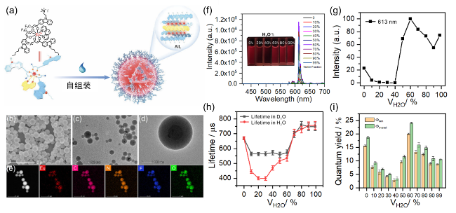
图4 (a) Eu配合物自组装的示意图; (b) Eu-NPs的SEM图像; (c, d) Eu-NPs的TEM图像; (e) Eu-NPs的元素分布图; (f, g) Eu配合物在丙酮/水中的发光光谱; (h) Eu配合物在丙酮/D2O或丙酮/H2O中的发光寿命; (i) Eu配合物在不同比例丙酮/水中的总发光量子产率(Φoverall)和从配体到Eu3+的能量转移效率(Φsen)Figure 4 (a) Schematic illustration of the self-assembly of Eu complexes; (b) SEM image of Eu-NPs; (c, d) TEM images of Eu-NPs; (e) Elemental mapping of Eu-NPs; (f, g) Luminescence spectra of Eu complexes in acetone/water; (h) Luminescence lifetimes of Eu complexes in acetone/D2O or acetone/H2O; (i) Total luminescence quantum yields (Φoverall) and energy transfer efficiencies from the ligand to Eu3+ (Φsen) of Eu complexes in acetone/water with different ratios |
2.1.2 稀土配合物与无机纳米材料的杂化组装
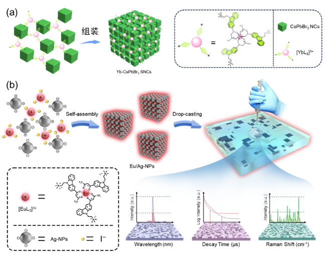
图6 (a) [YbL3]3+介导的CsPbBr3纳米晶自组装形成有序三维立方结构示意图; (b) 带负电的银纳米颗粒(Ag-NPs)通过静电作用组装于带正电的[EuL3]3+周围, 形成Eu/Ag-NPs, 从而增强荧光强度和拉曼信号并调控发光寿命, 随后将其涂覆于基底, 干燥后形成随机二维图案, 采用共聚焦荧光-拉曼联用系统对PUF标签进行读取Figure 6 (a) Schematic illustration of [YbL3]3+-mediated self-assembly of CsPbBr3 nanocrystals into ordered three-dimensional cubic superstructures; (b) Negatively charged Ag nanoparticles (Ag-NPs) assemble around positively charged [EuL3]3+ via electrostatic interactions to form Eu/Ag-NPs, which simultaneously enhance fluorescence intensity and Raman signals while modulating luminescence lifetimes. The resulting assemblies are then coated onto a substrate and dried to form random two-dimensional patterns. A confocal fluorescence-Raman combined system is employed to read the PUF tags |
2.2 原位配位
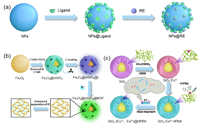
图7 (a) 基于稀土配合物构筑系列功能材料的方法示意图; (b) Fe3O4@mSiO2@MOF复合材料的合成过程及K+离子分离机理示意图; (c) 将Eu离子与HPBA封装于介孔二氧化硅中, 得到SiO2-(Eu2+, Eu3+)-HPBAFigure 7 (a) Schematic illustration of the methodology for constructing a series of functional materials based on rare-earth complexes; (b) Schematic illustration of the synthesis process of Fe3O4@mSiO2@MOF composites and the mechanism of K+ ion separation; (c) Encapsulation of Eu ions and HPBA into mesoporous silica to obtain SiO2-(Eu2+, Eu3+)-HPBA |
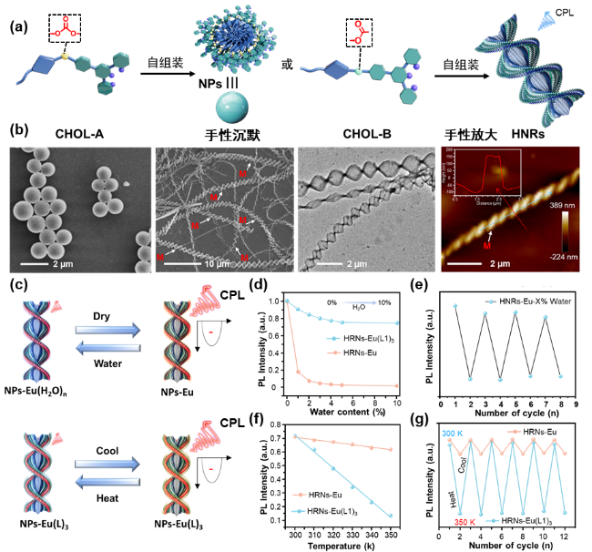
图8 (a) CHOL-A和CHOL-B分别组装形成纳米颗粒(NPs)和螺旋纳米带(HNRs)的示意图; (b) CHOL-A与CHOL-B组装体形貌; (c) HNRs-Eu和 HNRs-Eu(L1)3 CPL信号对于温度和湿度响应的示意图; (d~g) N HNRs-Eu和HNRs-Eu(L1)3的荧光强度在不同温度及水含量下的变化及循环性Figure 8 (a) Schematic illustration of the assembly of CHOL-A/B into nanoparticles (NPs) and helical nanoribbons (HNRs), respectively; (b) Morphology of the assemblies formed from CHOL-A/B; (c) Schematic illustration of the CPL signal responses of HNRs-Eu and HNRs-Eu(L1)3 to temperature and humidity; (d~g) Fluorescence intensity variations and reversibility of HNRs-Eu and HNRs-Eu(L1)3 under different temperatures and water contents |
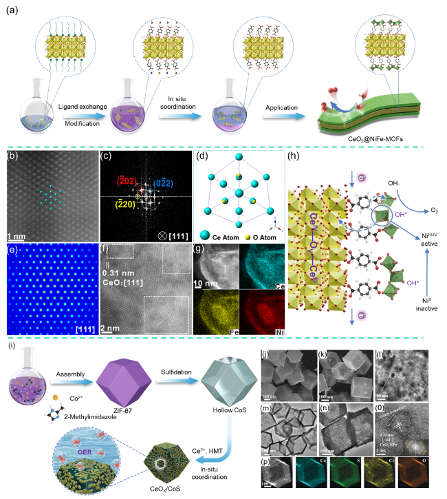
图9 (a) 在纳米材料表面上原位配位生长MOF示意图; (b) 沿CeO2 [111]方向观察的CeO2@NiFe-MOFs的原子级HAADF-STEM图像(c) 对应的(b)的傅里叶变换图案; (d) CeO2@NiFe-MOFs中CeO2的投影结构模型; (e) 经FFT滤波的原子分辨率模拟图像; (f) CeO2@NiFe-MOFs的高分辨TEM图像; (g) CeO2@NiFe-MOF异质结构的元素分布图; (h) 在反应过程中CeO2@NiFe-MOF异质结构中可能发生的电子转移路径; (i) CeO2/CoS杂化纳米结构合成过程示意图; CoS前驱体(j, m)和14.6% CeO2/CoS (k, n)的SEM和TEM图像; (l, o) 14.6% CeO2/CoS的高分辨TEM图像; (p) 14.6% CeO2/CoS的元素分布图Figure 9 (a) Schematic illustration of in situ coordination growth of MOF on the surface of nanomaterials; (b) Atomic-scale HAADF-STEM image of CeO2@NiFe-MOFs viewed along the [111] direction of CeO2; (c) Corresponding Fourier transform (FFT) pattern of (b); (d) Projected structural model of CeO2 within CeO2@NiFe-MOFs; (e) Atomic-resolution simulated image after FFT filtering; (f) High-resolution TEM image of CeO2@NiFe-MOFs; (g) Elemental mapping of the CeO₂@NiFe-MOF heterostructure; (h) Possible electron transfer pathways in the CeO2@NiFe-MOF heterostructure during the reaction process; (i) Schematic representation of the synthesis procedure for CeO2/CoS hybrid nanostructures. SEM and TEM images of the CoS precursor (j, m) and of 14.6 % CeO2/CoS (k, n); (l, o) High-resolution TEM images of 14.6 % CeO2/CoS; (p) Elemental mapping of 14.6 % CeO2/CoS |
2.3 微结构演化
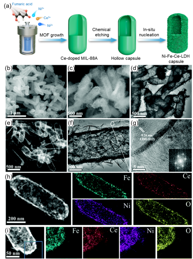
图10 (a) Ce掺杂MIL-88A辅助制备中空Ni-Fe-Ce LDH微胶囊示意图; (b, c) 30% Ce-NiFe-LDH微胶囊的SEM和(d) TEM图像; (e) 30% Ce-NiFe-LDH的HAADF-STEM图像; (f, g) HR-TEM图像和相应的SAED图案(插图); (h, i) 30% Ce-NiFe-LDH的单个微胶囊和局部放大微胶囊的HAADF-STEM图像及元素分布图Figure 10 (a) Schematic illustration of the preparation of hollow Ni-Fe-Ce LDH microcapsules assisted by Ce-doped MIL-88A; (b, c) SEM images and (d) TEM image of 30 % Ce-NiFe-LDH microcapsules; (e) HAADF-STEM image of 30 % Ce-NiFe-LDH, and (f, g) HR-TEM images with the corresponding SAED patterns (insets); (h, i) HAADF-STEM images and elemental mapping of a single microcapsule and a magnified region of the microcapsule for 30 % Ce-NiFe-LDH |
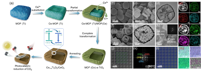
图11 (a) Ce1-xTixO2/CeO2制备的示意图; (b, c) MOF(Ti)和MOF(Ce)/a-TiO2-0.8的SEM图像; (d) MOF(Ce)/a-TiO2-0.8的TEM图像; (e) MOF(Ce)/a-TiO2-0.8的HAADF-STEM图像和元素分布图; (f) CTO/CeO2-0.8的SEM图像; (g) CTO/CeO2-0.8的TEM图像; (h) CTO/CeO2-0.8的HR-TEM图像及相应的SAED图案; (i) CTO/CeO2-0.8的HAADF-STEM图像和元素分布图; (j) CTO/CeO2-0.8中CTO部分的原子级HAADF-STEM图像; (k) (j)对应的FFT图案. (l) CTO/CeO2-0.8的FFT滤波原子分辨率模拟图像; (m) CTO/CeO2-0.8中CTO部分对应的能谱元素分布图Figure 11 (a) Schematic illustration of the preparation of Ce1-xTixO2/CeO2; (b, c) SEM images of MOF(Ti) and MOF(Ce)/a-TiO2-0.8, respectively; (d) TEM image of MOF(Ce)/a-TiO2-0.8; (e) HAADF-STEM image and elemental mapping of MOF(Ce)/a-TiO2-0.8; (f) SEM image of CTO/CeO2-0.8; (g) TEM image of CTO/CeO2-0.8; (h) HR-TEM image and the corresponding SAED pattern of CTO/CeO2-0.8; (i) HAADF-STEM image and elemental mapping of CTO/CeO2-0.8; (j) Atomic-scale HAADF-STEM image of the CTO region in CTO/CeO2-0.8; (k) Corresponding FFT pattern of (j); (l) FFT-filtered atomic-resolution simulated image of CTO/CeO2-0.8; (m) Corresponding EDS elemental mapping of the CTO region in CTO/CeO2-0.8 |
3 在智能发光材料及光转换材料和器件中的创新应用
3.1 在智能发光材料中的应用
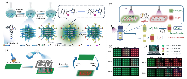
图12 (a) QDs-Eu(PBA)3AA的形成过程示意图; (b) 荧光图像展示双响应光学记录与加密, 包含图案设计流程及加密−解密机制; (c) 比色荧光时间−温度指示器及其多功能应用示意图; (d) 在不同温度和时间下加密信息的荧光图像; (e) 利用荧光颜色进行文本编码的图示Figure 12 (a) Schematic illustration of the formation of QDs-Eu(PBA)₃AA; (b) Fluorescence images showing dual-responsive optical recording and encryption, including the pattern design process and encryption-decryption mechanism; (c) Schematic illustration of the colorimetric fluorescent time-temperature indicator and its multifunctional applications; (d) Fluorescence images of encrypted information at different temperatures and times; (e) Illustration of text encoding using fluorescent colors |
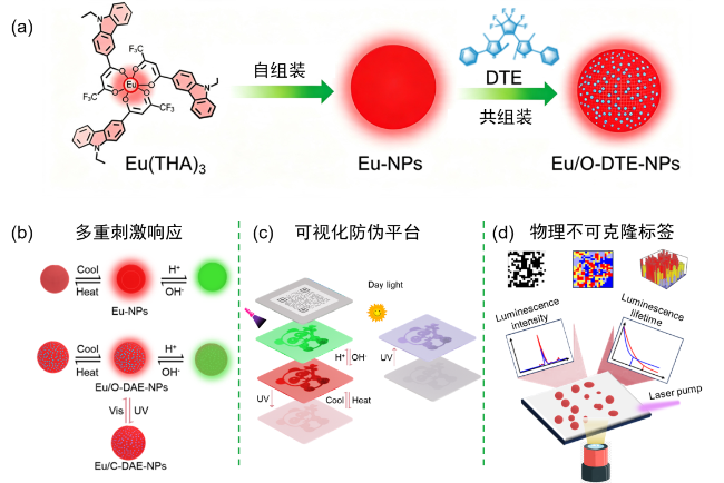
图13 (a) 铕配合物自组装成纳米粒子(Eu-NPs)及其与二噻吩乙烯共组装成杂化纳米粒子(Eu/O-DAE-NPs)的过程示意图; (b) Eu-NPs及Eu/O-DAE-NPs的多重刺激响应性质示意图; (c) 基于多重刺激响应型Eu/DTE-NPs体系的光学防伪平台; (d) 物理不可克隆函数(PUF)标签的示意图Figure 13 (a) Schematic illustration of the self-assembly of europium complexes into nanoparticles (Eu-NPs) and their co-assembly with dithienylethene into hybrid nanoparticles (Eu/O-DAE-NPs); (b) Schematic representation of the multi-stimuli-responsive properties of Eu-NPs and Eu/O-DAE-NPs; (c) Optical anti-counterfeiting platform based on the multi-stimuli-responsive Eu/DTE-NP system; (d) Schematic diagram of a (PUF) tag |
3.2 在智能诊疗探针中的应用
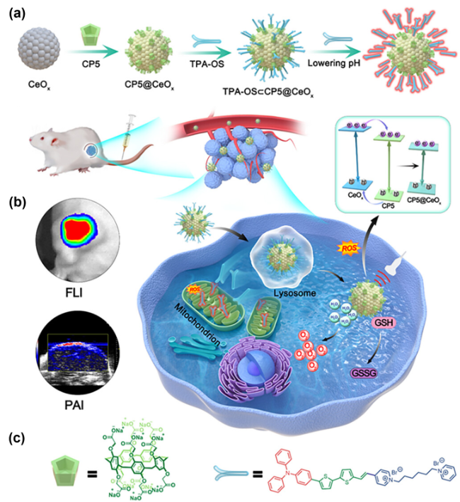
图14 TPA-OS⊂CP5@CeOx材料制备及声动力治疗可控过程的示意图 (a) TPA-OS⊂CP5@CeOx材料制备示意图; (b) 基于双细胞器靶向及界面工程增强声动力效应的体内肿瘤治疗示意图; (c) CP5与TPA-OS的化学结构Figure 14 Schematic illustration of the preparation of TPA-OS⊂CP5@CeOx materials and the controlled process of sonodynamic therapy (a) Schematic diagram of the preparation of TPA-OS⊂CP5@CeOx materials; (b) Schematic diagram of in vivo tumor therapy based on dual-organelle targeting and interface engineering-enhanced sonodynamic effects; (c) Chemical structures of CP5 and TPA-OS |
3.3 在光转换材料及器件中的应用
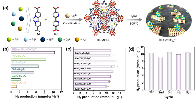
图15 (a) HEAs/CeO2/C的合成路线; (b) HEAs(10L)/CeO2/C, Pt/CeO2/C, Pd/CeO2/C, Ni/CeO2/C, Cu/CeO2/C, Ag/CeO2/C的光催化产氢速率; (c) HEAs(xL)/CeO2/C (x=5、7.5、10、12.5、15、20、25、30) 的光催化分解水产氢速率; (d) HEAs(10L)/CeO2/C的光催化产氢稳定性Figure 15 (a) Synthesis route of HEAs/CeO2/C; (b) Photocatalytic hydrogen production rates of HEAs(10L)/CeO2/C, Pt/CeO2/C, Pd/CeO2/C, Ni/CeO2/C, Cu/CeO2/C, and Ag/CeO2/C; (c) Photocatalytic water-splitting hydrogen production rates of HEAs(xL)/CeO2/C (x=5, 7.5, 10, 12.5, 15, 20, 25, 30); (d) Photocatalytic hydrogen production stability of HEAs(10L)/CeO2/C |
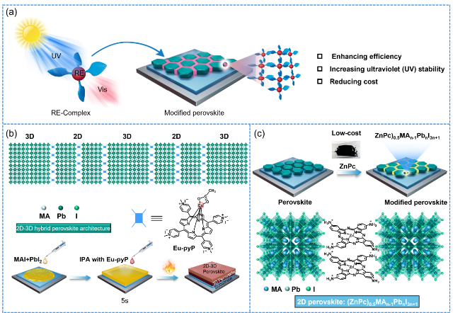
图16 (a) 稀土配合物用于增强钙钛矿太阳能电池抗紫外线和热稳定性的示意图; (b) 2D-3D杂化钙钛矿结构及用于构建2D-3D梯度的Eu-pyP滴涂策略示意图; (c) 由(ZnPc)0.5MAn−1PbnI3n+1缝合的MAPbI3薄膜及(ZnPc)0.5MAn−1PbnI3n+1的结构Figure 16 (a) Schematic illustration of rare-earth complexes for enhancing the UV and thermal stability of perovskite solar cells; (b) Schematic diagram of the 2D-3D hybrid perovskite structure and the drop-casting strategy using Eu-pyP to construct a 2D-3D gradient; (c) MAPbI3 thin film stitched with (ZnPc)0.5MAn−1PbnI3n+1 and the chemical structure of (ZnPc)0.5MAn−1PbnI3n+1 |
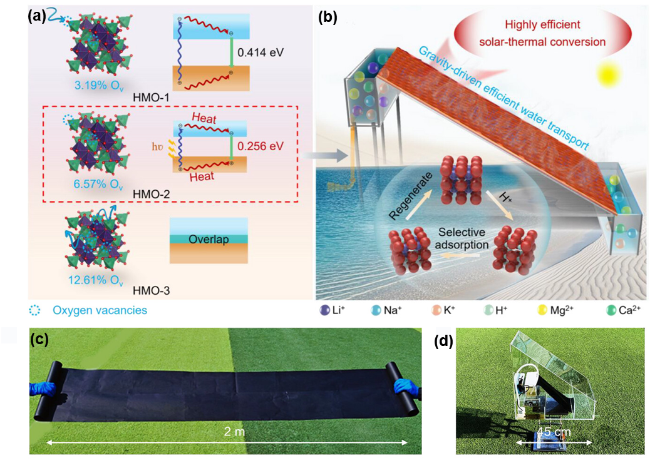


图17 (a) λ-MnO2带隙调控示意图; (b) Mn PE同时实现选择性锂离子捕获与淡水提取; (c) 大规模制备的Mn PE实物照片; (d) 定制的扩展蒸发单元Figure 17 (a) Schematic illustration of bandgap engineering of λ-MnO2; (b) Mn PE enabling simultaneous selective lithium-ion capture and freshwater extraction; (c) Photograph of the large-scale prepared Mn PE; (d) Customized expanded evaporation unit |