


1 引言
2 RM在放电-充电过程中的作用机理和电化学表现
2.1 放电过程
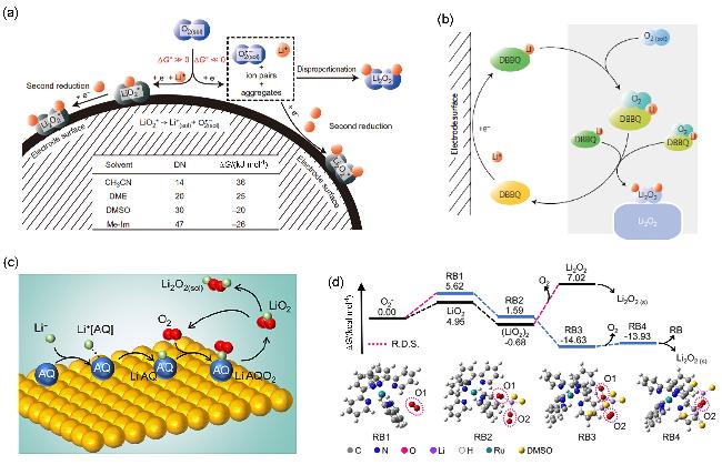
图1 (a)锂氧电池中O2还原示意图[溶液路径(蓝)和表面路径(灰)[54]]以及(b) DBBQ[34]、(c) AQ[55]和(d) RB[57]催化放电过程示意图Figure 1 (a) Schematic illustration of O2 reduction in a Li-O2 cell [the solution pathway (blue) and the surface pathway (gray)[54]], and schematics of discharge process catalyzed by (b) DBBQ[34], (c) AQ[55] and (d) RB[57] |
2.2 充电过程
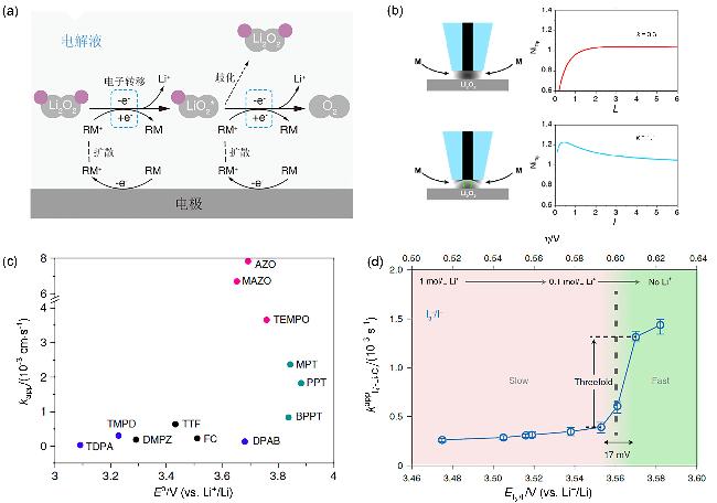
图2 (a) RM催化Li2O2分解示意图(电子转移步骤使用蓝色虚线框标出)、(b) SECM反馈曲线示意图[62]、(c)表观速率常数kapp与媒介体氧化还原电位E0的关系[62]及(d)含有LiTFSI的DMSO电解液中不同形式电位E ($\mathrm{I}_{3}^{-}$/I-)下$\mathrm{I}_{3}^{-}$氧化Li2O2的反应速率常数[63]Figure 2 (a) Schematic illustration of Li2O2 decomposition catalyzed by the RM (the electron transfer steps highlighted by blue dashed boxes), (b) schematics of SECM feedback approach curves[62], (c) dependence of the apparent rate constant, kapp, on the redox potential, E0, of the mediators[62], (d) the kapp of $\mathrm{I}_{3}^{-}$ oxidizing Li2O2 with various E ($\mathrm{I}_{3}^{-}$/I-) in DMSO electrolyte containing LiTFSI[63] |
3 RM的分类及优缺点(按活性中心分类)
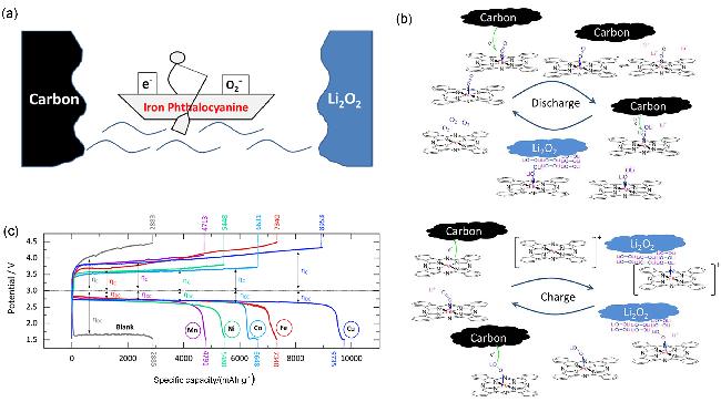
3.1 金属中心化合物
3.2 有机小分子
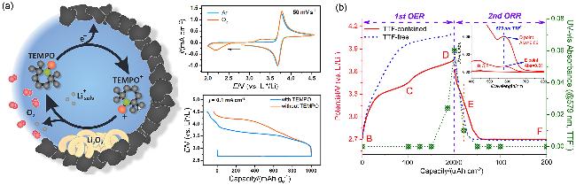
图4 (a) TEMPO催化锂氧电池充电过程的示意图和电化学性能[73]及(b)多孔碳电极在含TTF的Li-DMSO电解质中循环时观察到不同状态下(用字母B到F标记)的紫外可见光谱[78]Figure 4 (a) Schematics and electrochemical performance of charging process catalyzed by TEMPO in Li-O2 batteries[73], and (b) UV-vis spectra observed at different states (marked by letters from B to F) during cycling of the porous carbon electrode in the TTF-containing Li-DMSO electrolyte[78] |