


1 Introduction
Metal-organic frameworks (MOFs) have attracted sustained interest as tunable solid-state photoluminescent materials owing to their modular architectures, tailorable local environments, and the ability to integrate luminescent components into well-defined crystalline lattices.[1-2] Compared with conventional molecular emitters, MOFs provide a unique platform for correlating photophysical behaviors with precise structural parameters, offering opportunities in sensing, optoelectronics, information encryption, and stimuli-responsive luminescence.[3-6] However, rational prediction and control of the emission properties of MOFs remain challenging because their excited states can be highly sensitive to subtle changes in coordination geometry, intermolecular contacts, and electronic coupling between metal nodes and organic linkers.[7-10]
Among luminescent MOFs, Cu(I)-based frameworks are particularly appealing due to the d10 electronic configuration of Cu(I), which enables diverse emissive pathways, including ligand-centred emission, ligand-to-metal/metal- to-ligand charge transfer, and cluster-centred excited states.[11-13] In Cu(I) halide systems, the halide anion not only dictates coordination geometry and framework assembly, but also contributes directly to the frontier electronic structure through Cu—X (X=Cl, Br, I) hybridization.[14-15] Moreover, Cu…Cu “cuprophilic” interactions, which often emerge when the Cu…Cu distances become sufficiently short to stabilize low-energy metal-centred or cluster-centred states, markedly modulate band-edge positions and emission energies.[16-18] These features make Cu(I)-halide MOFs attractive model systems for elucidating structure-property relationships in solid-state luminescence.
Despite rapid progress, systematic studies that simultaneously address (i) thermal stability, (ii) solid-state emission, and (iii) electronic-structure origins within a closely related Cu(I)-halide MOF series remain limited. In many reported cases, changes in Cu(I)-halide framework structure can regulate the distance, orientation, and rigidity of the luminescent units, thereby further affecting energy migration, excitonic coupling, and radiative/non-radiative transition processes.[19] At the same time, solvent molecules or other guests within the pores may also induce significant changes in the emission wavelength and intensity through hydrogen-bonding interactions, variations in local polarity, and host-guest energy or electron transfer.[20] For these reasons, in many previously reported systems, the non-monotonic spectral shifts observed with compositional variation are often accompanied by the coupled evolution of multiple variables, making the underlying mechanism difficult to clarify directly.[21] Importantly, these variables also influence thermal robustness, yet thermal stability is often discussed separately from photophysics, leaving an incomplete picture of how halide identity governs both framework stability and electronic transitions. Halide substitution is an effect approach to rationalize luminescence tuning for topological fixed framework to eliminate interference and reveal inherent laws.[22-24] Therefore, it is highly desirable to construct a set of structurally comparable Cu(I)-halide MOFs and interrogate their luminescence and stability with complementary theory.
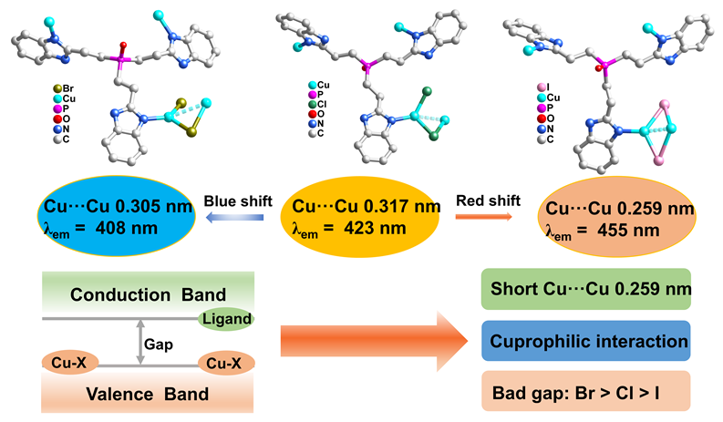
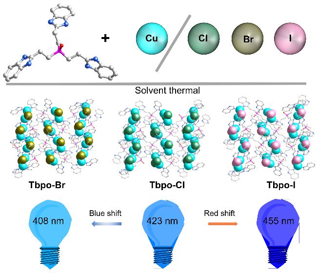
In this work, we prepared three isoreticular Cu(I)-halide MOFs, Tbpo-Cl/Br/I, by solvothermal assembly of a tripodal benzimidazole linker (Tbpo) with CuX (X=Cl, Br, I). Tbpo contains a phosphoryl (P=O) core and three benzimidazole arms connected through ethylene spacers, enabling multidentate coordination while retaining sufficient conformational flexibility. Importantly, all three materials adopt the same two-dimensional topology (Figure 1), allowing a direct comparison of halide-dependent structure-property relationships. Thermogravimetric analysis reveals a gradual decrease in thermal stability with increasing halide radius, consistent with the elongation and softening of Cu—X bonds and the weakening of hydrogen-bonding interactions. The solid state emission maxima are located at 423 nm (Tbpo-Cl), 408 nm (Tbpo-Br), and 455 nm (Tbpo-I), showing a distinct non-monotonic dependence on the halide. To clarify the electronic origin of this behaviour, we carried out density functional theory (DFT) calculations together with density of states (DOS) and partial density of states (PDOS) analyses, which indicate a Cu—X hybridized valence-band edge and a ligand-centred conduction-band edge. The results further suggest that strong cuprophilic interactions become relevant when the Cu…Cu distance decreases below 0.280 nm, providing a plausible basis for band-gap narrowing and the red-shifted emission observed for the iodide analogue. Overall, this topology-controlled series offers a coherent picture of how halide identity, framework rigidity, and Cu…Cu interactions jointly determine both thermal robustness and luminescence in Cu(I)-halide MOFs.
2 Result and discussion
2.1 Crystal structure of Tbpo-Cl/Br/I
Single-crystal X-ray diffraction shows that Tbpo-Cl crystallizes in the monoclinic space group P21/c (see Supporting information, Table S1). Its framework is constructed from Cu2Cl2 units and the tripodal linker Tbpo. Within the Cu2Cl2 motif, one Cu(I) center is coordinated by one Tbpo ligand and two chloride ions, whereas the other Cu(I) center is bound to two Tbpo ligands and one chloride ion. The two chloride ions bridge the two Cu centers in a κ1-κ2-μ2 coordination mode, giving a distorted tetrahedral environment. The Cu—Cl bond lengths fall in the range 0.226—0.237 nm. The torsion angle N…Cu—Cl…Cu is 128.7°, and the angles ∠Cl(1)-Cu(1)-Cl(2) and ∠Cu(1)-Cl(2)-Cu(2) are 108.5° and 86.0°, respectively (Figure 2a).
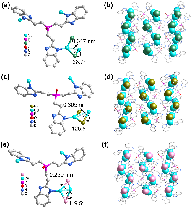
Figure 2 The crystal structure of Tbpo-Cl/Br/I. (a) The coordination mode of Tbpo with Cu2Cl2; (b) 2D layer structure of Tbpo-Cl; (c) The coordination mode of Tbpo with Cu2Br2; (d) 2D layer structure of Tbpo-Br; (e) The coordination mode of Tbpo with Cu2I2; (f) 2D layer structure of Tbpo-I |
The Cu…Cu separation is 0.317 nm, suggesting negligible cuprophilic interaction. Each Tbpo linker connects three Cu centers in a κ1-κ1-κ1-μ3 coordination mode, and the linkage between Tbpo and Cu2Cl2 generates a two-dimensional layer with fes topology (see Supporting information, Figures S1, 2b). Tbpo-Br also crystallizes in the monoclinic space group P21/c (Table S2), and adopts the same overall coordination connectivity as Tbpo-Cl. The Cu2Br2 cluster is bridged by two bromide ions in an analogous κ1-κ2-μ2 manner. The Cu—Br distances range from 0.233 to 0.249 nm, with a torsion angle N…Cu—Br…Cu of 125.5°. The ∠Br(1)-Cu(1)-Br(2) and ∠Cu(1)-Br(2)- Cu(2) are 110.8° and 77.6°, respectively (Figure 2c). The Cu…Cu distance decreases to 0.305 nm relative to Tbpo- Cl, while the resulting framework still forms a two-dimensional fes net (see Supporting information, Figures S1, 2d). The Tbpo-I crystallizes in the triclinic space group Pī (see Supporting information, Table S3). However, the coordination mode of Cu2I2 does differ from both of them. Each I atom bridges two Cu(I) centers, forming Cu2I2 moieties. And two Cu(I) centers show 3-coordinated and 4-coordinated coordination modes, respectively, where Cu(1) coordinates two I atoms and one Tbpo, Cu(2) coordinates two I atoms and two Tbpo, the double I atoms connect Cu centers in κ2-κ2-μ2 coordination mode (Figure 2e). The Cu—I ranges from 0.253 to 0.273 nm with torsion angle of N…Cu—I…Cu (118.5°) and ∠I(1)-Cu(1)-I(2) and ∠Cu(1)-I(2)-Cu(2) are 118.5° and 58.9°, respectively. Cu…Cu forms smallest distance 0.259 nm compared with Tbpo-Cl/Br. Similarly, Tbpo-I also displays fes topology structure (see Supporting information Figure S1, Figure 2f).
According to crystal structures of Tbpo-Cl/Br/I, the torsion angles as well as Cu…Cu distances decrease in the order of Tbpo-I<Tbpo-Br<Tbpo-Cl. It is attributed to the increasing halide ionic radii (cf. ionic radii, Cl-: 0.181 nm, Br-: 0.196 nm, and I-: 0.220 nm),[25] which means that an increase in the halide ionic radius reduces the structural distortion, and thereby enhances the planarity of the coordination between Tbpo and Cu2X2 (X=Cl/Br/I). Furthermore, Cu…Cu distance of Tbpo-I is less than 0.280 nm (twice the van der Waals (vdW) radius of Cu atom), strong cuprophilic interactions [the closed‐shell d10-d10 Cu(I)- Cu(I) interactions] may exist within Tbpo-I.[26-28]
2.2 Hirshfeld surface analysis
The supramolecular packing of the Tbpo-Cl/Br/I series is mainly controlled by intermolecular contacts rather than changes in the primary coordination environment. To examine the contacts, we used Hirshfeld surface (HS) analysis, where the crystal environment around a reference molecule is partitioned and then visualized by mapping the surface over dnorm. In the HS(dnorm) representation, red regions mark contacts that are shorter than the sum of the relevant vdW radii, while white and blue areas correspond to contacts close to or longer than vdW separations.[29] The HS(dnorm) maps for Tbpo-Cl, Tbpo-Br, and Tbpo-I are broadly comparable, which agrees with their isostructural nature, but differences in the location and intensity of the red patches indicate that halide substitution subtly redistributes the dominant short contacts. Notably, a common feature in all three solids is a set of red spots associated with O…H contacts, consistent with a persistent hydrogen-bonding network involving lattice water. The P=O group acts as the key acceptor site, giving rise to P=O…H—O interactions whose overall contributions remain similar across Tbpo-Cl/Br/I (Figure 3). This is also reflected in the 2D fingerprint plots: the O…H/H…O region shows a nearly unchanged shape and extent, and the strong participation of water-derived hydrogen atoms supports the view that water plays a comparable structural role in each lattice. Taken together, these observations suggest water-mediated P=O…H—O motif acts as a conserved “scaffold” that helps maintain the packing pattern throughout the series.
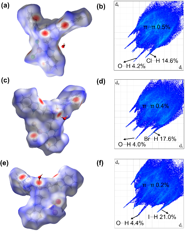
Figure 3 The Hirshfeld surface analysis of Tbpo-Cl/Br/I. (a) Hirshfeld surface plotted over dnorm for Tbpo-Cl; (b) 2D fingerprint plot of Tbpo-Cl; (c) Hirshfeld surface plotted over dnorm for Tbpo-Br; (d) 2D fingerprint plot of Tbpo-Br; (e) Hirshfeld surface plotted over dnorm for Tbpo-I; (f) 2D fingerprint plot of Tbpo-I |
Halide-related hydrogen bonding, however, evolves more noticeably. The fingerprint plots show that the fraction of surface contacts assigned to N—H…X increases from Cl to Br to I. At the same time, the N—H…X distances lengthen, following the order N—H…Cl (0.238 nm, 164.0°)<N—H…Br (0.252 nm, 165.4°)<N—H…I (0.276 nm, 167.0°). This trend is readily rationalized by the increasing size of the halide anion: as the ionic radius increases down the group, the closest feasible H…X separations shift outward even when the overall packing motif is retained. Importantly, HS percentages quantify how frequently a given contact appears on the surface (and how much surface area it occupies), rather than the strength of a single interaction.
Therefore, a larger, more polarizable iodide can account for a larger share of the HS contacts through many accessible N—H…I approaches, even if each contact is geometrically longer. Finally, the fingerprint plots provide little evidence for meaningful π…π stacking, as the characteristic C…C features expected for strong aromatic stacking are weak or absent (Figure 3). Overall, the packing is dominated by the conserved water-assisted P=O…H—O network, while halide substitution primarily tunes the prevalence and geometry of N—H…X contacts without introducing a new dominant stacking interaction.
2.3 X-ray powder diffraction analysis, thermal stability and BET analysis
Powder X-ray Diffraction (PXRD) patterns of as-synthesized bulk crystals for Tbpo-Cl/Br/I are consistent simulated PXRD patterns (see Supporting information, Figure S2), indicating that the three MOFs are high purity. Furthermore, PXRD patterns for the Tbpo-Cl/Br/I still maintain good crystallinity compared with the fresh samples after exposure to ambient air, moisture, and solvents such as acetonitrile (MeCN), N,N-dimethylformamide (DMF), methanol (MeOH) and ethanol (EtOH) for three days, demonstrating structures stability of them.[30] Thermogravimetric analysis (TGA) curves were conducted in N2. The structural collapse of Tbpo-Cl/Br/I start at 291.1 ℃, 202.3 ℃ and 134.6 ℃, respectively (see Supporting information, Figure S4). The thermal stability follows Tbpo-I<Tbpo-Br<Tbpo-Cl. This may be attributed to the bond length of Cu—X and hydrogen interactions.[31] As the halide is varied from Cl to Br to I, the Cu—X bond typically elongates due to the increased anion size. This elongation reduces the effective orbital overlap within Cu—X linkage and, correspondingly, decreases the bond stiffness, rendering the Cu—X connection more compliant.[32] Under thermal excitation, a “softer” Cu—I framework is therefore more susceptible to amplified vibrational motion and local geometric distortion, which can accumulate into cooperative lattice strain. Consequently, even for an identical topology and coordination mode, the Cu—I analogue tends to lose long-range crystallographic order at a lower temperature than the Cu—Cl and Cu—Br counterparts, consistent with its reduced resistance to thermally induced framework deformation and collapse. Moreover, the pore volumes are 0.016, 0.014, 0.014 mL/g for Tbpo-Cl/Br/I, respectively (see Supporting information, Figure S3). The three MOFs exhibit nearly identical pore volumes, which can be attributed to their identical topological structures and the use of the same ligands.
2.4 Luminescence properties and DFT calculation
Solid-state photoluminescence measurements were carried out for Tbpo and the corresponding MOFs Tbpo-Cl/ Br/I. The free ligand Tbpo shows an emission maximum at 329 nm, which can be assigned to the ligand-centred π*→π transition.[33] In contrast, the three MOFs exhibit markedly longer-wavelength emissions at 423 nm (Tbpo-Cl), 408 nm (Tbpo-Br), and 455 nm (Tbpo-I) under excitation at 340 nm (Figure 4a). Notably, the emission maxima do not follow a simple monotonic trend among Tbpo-Cl, Tbpo-Br, and Tbpo-I, indicating that halide substitution influences the emissive states in a non-trivial manner. At low temperature (150 K), the three copper halide cluster-based MOFs exhibit higher maximum luminescence intensity (see Supporting information, Figure S7). Furthermore, The photoluminescence quantum yields in room temperature of Tbpo-Cl/Br/I are 2.75%, 2.61%, 2.04%, respectively, and at 150 K, quantum yields of Tbpo-Cl/Br/I are 3.15%, 2.96%, 2.50%, respectively (see Supporting information, Table S4). The three halogenated MOFs at 150 K exhibit longer fluorescence lifetimes that are 12.7, 12.2 and 10.8 ns for Tbpo-Cl/Br/I compared with fluorescence lifetimes (10.1, 9.0 and 8.1 ns) for Tbpo-Cl/Br/I at room temperature, respectively (see Supporting information, Figure S8).
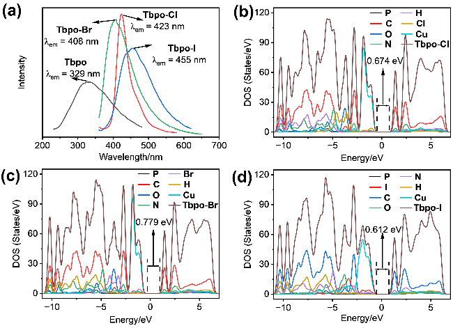
These results indicate that cooling effectively suppresses non-radiative decay pathways related to intramolecular vibrations, ligand torsion, and thermal perturbation of the framework, thereby favoring radiative deactivation of the excited-state energy.[34] Meanwhile, the restricted excited-state structural relaxation and altered stabilization of the local charge-transfer state at low temperature lead to emission from a relatively higher-energy configuration, resulting in a slight blueshift.[35-36] The prolonged fluorescence lifetime is consistent with the increased quantum yield, further confirming that cooling suppresses non-radiative decay and enhances the relative contribution of radiative transitions to the overall deactivation process.[37-38] As the halide becomes heavier, the heavy-atom effect and spin-orbit coupling in the copper halide clusters become stronger, thereby promoting intersystem crossing (ISC) and might leading to shorter fluorescence lifetimes and lower quantum yields.[39] This is consistent with the experimental observations. However, the emission lifetime remains in the nanosecond range even at low temperature, rather than extending into the microsecond or millisecond regime, indicating that phosphorescence is not the dominant origin of the main emission band.[40]
Under the same test conditions as those used for PXRD, no significant changes were observed in either the peak positions or the intensities of the maximum solid-state luminescence emission spectra of the three copper halide cluster-based MOFs compared with their initial states, further confirming their structural stability. To clarify the origin of this behavior, we further analyzed the electronic structures using DFT calculations.[41]
The electronic structures of the halide-substituted Cu(I)-benzimidazole MOFs were analyzed to rationalize the experimentally observed photoluminescence (PL) variation and, in particular, the non-monotonic band-gap evolution across the series. Band gaps extracted from the total density of states (TDOS) by identifying the zero-DOS window around the Fermi level (set at 0 eV) reveal a clear trend of Tbpo-Br>Tbpo-Cl>Tbpo-I, with Eg=0.779 eV (Br), 0.674 eV (Cl), and 0.612 eV (I) (Figures 4b—4d). According to UV-Vis diffuse reflectance spectra of the three MOFs, the opitcal band gaps of Tbpo-Cl, Tbpo-Br, and Tbpo-I are estimated to be 0.82, 0.95, and 0.68 eV, respectively (see Supporting information, Figure S9), they remain consistent with the theoretical trend (Tbpo-Br>Tbpo-Cl>Tbpo-I).
Notably, the corresponding PL maxima appear at 408 nm (Tbpo-Br), 423 nm (Tbpo-Cl), and 455 nm (Tbpo-I), that is the emission energy follows the order Tbpo-Br>Tbpo-Cl>Tbpo-I, consistent with the computed band-gap ordering. Although absolute DFT band gaps are typically underestimated relative to optical transition energies, the agreement in trends provides strong support that the band- edge electronic structures govern the observed optical response. Projected DOS (PDOS) analysis further clarifies the orbital and element origins of the band edges. For all three MOFs, the valence band maximum (VBM) is predominantly Cu-derived, with significant halide participation, whereas the conduction band minimum (CBM) is overwhelmingly ligand-centred. Quantitatively, integration within a 0.3 eV window below the VBM indicates that the VBM is dominated by Cu contributions of 84.9% (Tbpo-Cl), 82.6% (Tbpo-Br), and 81.0% (Tbpo-I), accompanied by appreciable halide contributions of 9.8% for Cl, 11.3% for Br, and 11.2% for I. The remaining fraction near the VBM arises mainly from the linker (N and C). Consistently, the angular momentum resolved DOS shows that the VBM region is d-dominated, with d contributions of approximately 83.0% (Cl), 81.0% (Br), and 80.0% (I), while p contributions increase modestly from 15.4% (Cl) to 17.2% (Br) and 18.0% (I). Taken together, these results support a robust assignment of the VBM as a Cu-d-centred edge with halide-p mixing, i.e., a Cu—X hybridized valence band edge across the series (see Supporting information, Figures S10—S12).
In contrast, the CBM, integrated over a 0.3 eV window above the band edge, is consistently ligand-centred, with C (80%—81%) and N (12%—13%) dominating its composition in all three materials, whereas Cu contributions remain minor (1.3%—1.4%) and halide contributions are negligible (≤0.5%). Angular-momentum analysis corroborates this picture: the CBM is p-dominated (95% p for all three MOFs), consistent with benzimidazole π* character. Therefore, the halide identity modulates the electronic structure primarily by influencing (i) the Cu—X hybridized VBM and (ii) the energetic alignment of the ligand- centred CBM, rather than by directly contributing halide- centred conduction-band states. A key outcome of the TDOS analysis is that the VBM positions are remarkably similar across the series (approximately -0.166 to -0.174 eV), whereas the CBM shifts substantially, providing an important mechanistic clue. Specifically, the CBM is highest for Tbpo-Br (0.613 eV), intermediate for Tbpo-Cl (0.507 eV), and lowest for Tbpo-I (0.438 eV). This indicates that the non-monotonic band-gap trend is driven largely by a halide-dependent reorganization of the ligand π* manifold (CBM), rather than by large displacement of the Cu—X hybrid valence edge. Such behavior is consistent with the fact that changes in coordination geometry and framework torsion can strongly affect orbital alignment and electronic coupling between the inorganic node and the organic linker, thereby shifting the energies of ligand-centred frontier states.[42]
When these electronic trends are interpreted in light of structural descriptors, the origin of the non-monotonic band gaps becomes clearer. Moving from Tbpo-Cl to Tbpo-Br, the coordination distortion increases and the torsion angle decreases from 128° (Tbpo-Cl) to 125° (Tbpo-Br), accompanied by an increase in the Cu—X bond length from 0.278 nm (Cu—Cl) to 0.233 nm (Cu—Br). These structural changes reduce effective orbital alignment and overlap, which promotes electronic localization and bandwidth narrowing near the band edges. According to the charge density difference analysis, the average number of electrons lost by the Cu atom is 4.69 e in Tbpo-Cl and 2.66 e in Tbpo-Br, respectively. Compared with Tbpo-Cl, the smaller electron loss of Cu in Tbpo-Br indicates weaker charge transfer and a less pronounced redistribution of electron density (see Supporting information, Figure S14a),[43] which may imply a more localized character of the relevant electronic states in Tbpo-Br (see Supporting information, Figure S14b).[44] In practical terms, such localization can raise the energy of the ligand-centred π* edge (CBM upshift), consistent with Tbpo-Br exhibiting the highest CBM and therefore the largest band gap. Although the Cu…Cu distance shortens slightly from 0.317 nm (Tbpo-Cl) to 0.305 nm (Tbpo-Br), this separation remains outside the regime typically associated with strong cuprophilic interactions, and the PDOS indicates that Tbpo-Br retains a predominantly ligand-centred CBM with only minor Cu involvement. Consequently, for Tbpo-Br, distortion-controlled localization is the dominant factor, yielding both the widest band gap and the most blue-shifted PL emission (408 nm). The iodide analogue exhibits a distinct balance of effects. Structurally, Tbpo-I shows the shortest Cu…Cu distance (0.259 nm), together with the longest Cu—X bond length (Cu—I=0.255 nm) and the smallest torsion angle (119°). The markedly shortened Cu…Cu separation is expected to enhance cuprophilic interactions and promote metal-centred coupling, which can introduce additional low energy pathways and stabilize band-edge states through increased metal-to-metal or metal-to-halide electronic communication. According to the PDOS analysis, cuprophilic interactions in Tbpo-I promote significant overlap between the p orbitals of I and the d orbitals of Cu (see Supporting information, Figure S13). In the DOS, this manifests as a lower CBM (0.438 eV) and the smallest band gap (0.612 eV), despite the fact that increased torsion and reduced orbital overlap might otherwise favour localization. Importantly, the PDOS still shows a ligand-centred CBM, implying that the principal iodide-induced effect is not the formation of halide-centred conduction states but rather a realignment of the frontier levels in a manner that decreases the effective band gap. This electronic picture is directly reflected in the red-shifted emission of Tbpo-I.
Overall, combining TDOS-derived band edges with quantitative PDOS partitioning establishes a consistent structure-electronic-optical relationship: the band edges remain Cu—X hybridized at the VBM and ligand-centred at the CBM, while the non-monotonic band gap sequence arises from the interplay between distortion/torsion controlled localization (most pronounced in Tbpo-Br, raising the CBM) and Cu…Cu interaction-enabled level reorganization (most significant in Tbpo-I, lowering the CBM and narrowing the gap). The PL maxima (408, 423, and 455 nm) follow the same order as the computed gaps, confirming that halide substitution modulates emission primarily by these coupled structural and electronic effects.
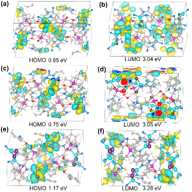
To further elucidate the luminescence mechanism of Tbpo-Cl/Br/I, the frontier molecular orbitals (HOMO and LUMO) are analyzed by DFT calculations. Relative to the free ligand Tbpo, the emission maxima of Tbpo-Cl/Br/I are systematically red-shifted. The calculated LUMOs of all three frameworks are primarily localized on the benzimidazole moieties of Tbpo, whereas corresponding HOMOs are mainly distributed over the Cu2X2 (X=Cl, Br, I) units (Figure 5). This spatial separation of the frontier orbitals suggests that the optical transition has a pronounced charge-transfer character.[45] Consequently, the observed red shifts are most plausibly attributed to an enhanced charge-transfer process between the Tbpo linker and the Cu2X2 clusters in Tbpo-Cl/Br/I.


3 Conclusion
In summary, three new Cu(I)-halide MOFs, Tbpo-Cl/ Br/I, were obtained via solvothermal assembly of the Tbpo linker with CuX (X=Cl, Br, I), giving frameworks with closely related coordination motifs. The thermal stability decreases progressively with increasing halide radius, which can be rationalized by the elongation of Cu—X bonds that reduces framework rigidity, together with the concomitant weakening of intermolecular hydrogen- bonding interactions. DFT calculations further reveal a Cu—X hybridized valence-band edge (VBM) for all three MOFs. Importantly, when the Cu…Cu separation falls below 0.280 nm, strengthened cuprophilic interactions promote the formation of low-energy Cu-centred states and narrow the band gap. This electronic-structure evolution correlates well with the observed photoluminescence behaviors, highlighting the cooperative roles of halide identity, framework rigidity, and Cu…Cu interactions in governing the optical and thermal properties of this series.
4 Experimental section
4.1 Preparation of compound Tbpo-Cl
Ligand Tbpo (0.01 mmol), CuCl (0.15 mmol) and HCOOH (10 μL) were added in CH3OH/CH3CN (V∶V=1∶5) solution in a teflon-lined autoclave. The resulted mixture was heated at 120 ℃ for 48 h, and then allowed to room temperature (r.t.). Light yellow crystals were obtained and were collected after filtration. Yield: 35% (based on ligand Tbpo). CCDC number: 2516618.
4.2 Preparation of compound Tbpo-Br
Ligand Tbpo (0.01 mmol), CuBr (0.15 mmol) and HCOOH (12 μL) were added in DMF/CH3CN (V∶V=1∶5) solution in a teflon-lined autoclave. The resulted mixture was heated at 120 ℃ for 48 h, and then allowed to r.t. Light yellow crystals were obtained and were collected after filtration. Yield: 38% (based on ligand Tbpo). CCDC number: 2516619.
4.3 Preparation of compound Tbpo-I
Ligand Tbpo (0.01 mmol), CuI (0.15 mmol), KI (0.15 mmol), and HCOOH (10 μL) were added in DMF/CH3CN/ H2O (V∶V∶V=1∶5∶0.5) solution in a teflon-lined autoclave. The resulted mixture was heated at 140 ℃ for 48 h, and then allowed to r.t. Light yellow crystals were obtained and were collected after filtration. Yield: 40% (based on ligand Tbpo). CCDC number: 2516620.
Experimental details, crystal data, additional catalysis information are concluded in supporting information.
(Cheng, F.)