


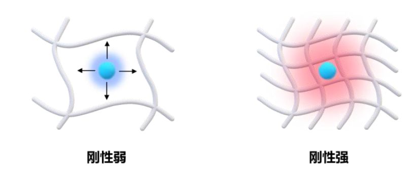
1 传统刚致荧光变色分子
1.1 分子内电荷转移(ICT)型荧光探针
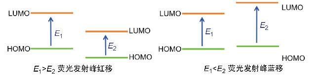
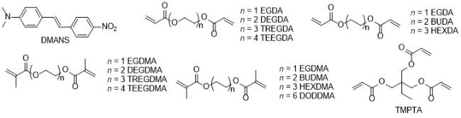
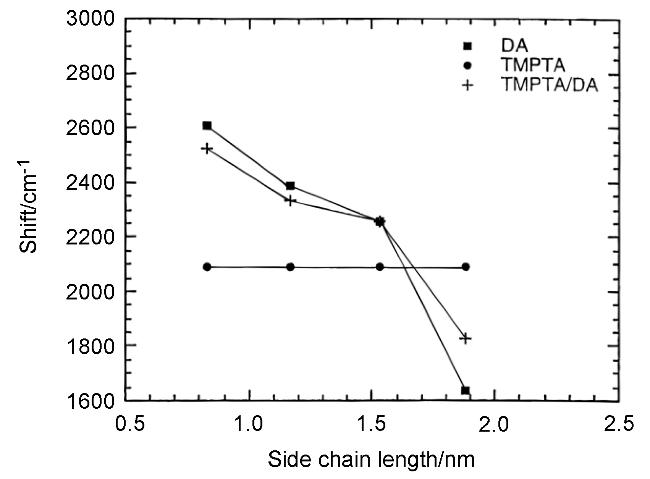
1.2 扭曲分子内电荷转移型荧光探针
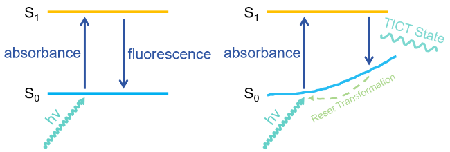
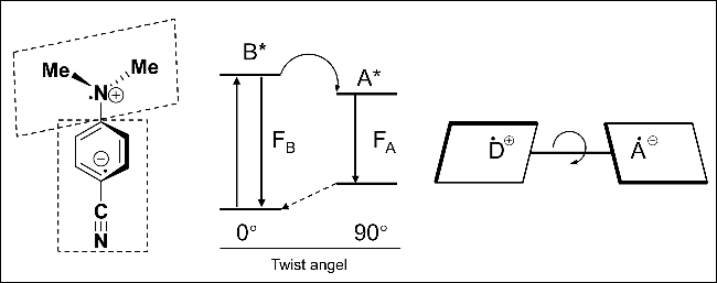
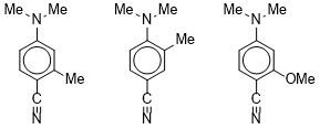
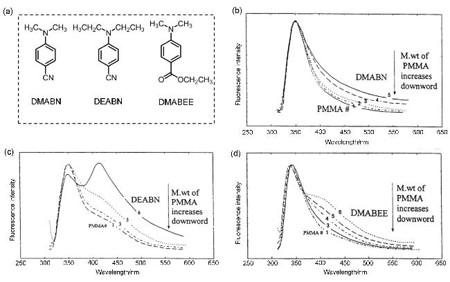
1.3 准分子型荧光探针
1.4 荧光共振能量转移(FRET)型荧光探针
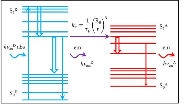
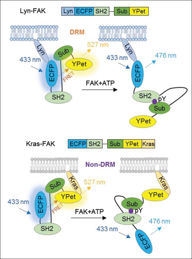
图10 利用FAK生物传感器的构象变化检测两个不同质膜微区DRM (Lyn-FAK)和非DRM (Kras-FAK)处的FAK信号的底层机制的示意图Figure 10 Schematic diagram of the underlying mechanism detecting FAK signals at two different plasma membrane microregions DRM (Lyn-FAK) and non-DRM (Kras-FAK) through conformational change of the FAK biosensor |
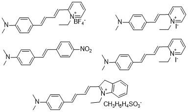
1.5 D-π-A+X-有机盐型荧光探针
1.6 金属-配体间的电荷转移(MLCT)型探针
2 新型刚致荧光变色分子
表1 新型刚致变色现象与聚集诱导发射(AIE)、簇发光(CTE)、聚合诱发发射(PIE)和超分子组装诱发发射(SIE)的主要区别Table 1 Key differences of new-rigidochromism with respected to aggregation-induced emission (AIE), clusteringtriggered emission (CTE), polymerization induced emission (PIE), and supramolecularassembly induced emissions (SIE) |
| Component | Fluorescent intensity | Fluorescent color | Chemical structure | Mechanism | |
|---|---|---|---|---|---|
| Anti-rigidochromism | Fluorophore+non- conjugated polymer | NAa | Red shift | Planar, rigid, conjugated fluorophore with various polymers | CTC and TSCb |
| Rigidochromism | NAa | Blue shift | Rotatable, conjugated, D-A structured fluorophores | TICT, ICT, Excimer, MLCT | |
| AIE | Fluorophore | Increase | NAa | Rotatable, vibrable, conjugated fluoro- phores | RIRc, RIVd |
| CTE | Non-conjugated polymer | Increase | NAa | Polymer containing NH2, OH, C=O, and other groups with n and π electrons | TSCb |
| PIE | Non-conjugated polymer | Increase | Red shift | Specific monomers/functional groups (e.g., borane, aldehyde, dichlorobenzo- phenone) | TSCb |
| SIE | Fluorophore guest+ host | NA | Red shift | Well-defined fluorophores and specific hosts (e.g, macrocycles, molecular cages) | RIR, dimerization, ICT |
a NA: no clear trend, may change in both directions; b TSC: Through space conjugation; c RIR: Restriction in rotation; d RIV: Restriction in vibration. |
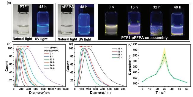
图15 (a) PTF1/pPFPA在甲苯/四氢呋喃(体积比1∶2)溶液中共组装过程的荧光图像以及相同条件下PTF1和pPFPA单独溶液48 h后的荧光图像(PTF1的浓度为7.5×10⁻⁶ mol/L, PTF1/PFPA物质的量之比为1∶5000); (b, c)沉淀前后四氢呋喃(THF)中PTF1/pPFPA共组装直径变化的DLS表征; (d)顶层溶液中PTF1/pPFPA共组装的平均直径随时间的分布Figure 15 (a) Fluorescence images of PTF1/pPFPA during the co-assembly process in toluene/THF (volume ratio 1∶2) solution and after 48 h of PTF1 and pPFPA alone solution under the same conditions (molar concentration of PTF1 is 7.5×10⁻⁶ mol/L, and the molar ratio of PTF1/PFPA is 1∶5000); (b, c) DLS characterization of the variation of PTF1/pPFPA coassembly diameter in THF before and after precipitation; (d) distribution of the mean diameter of PTF1/pPFPA coassembled in the top solution with time |
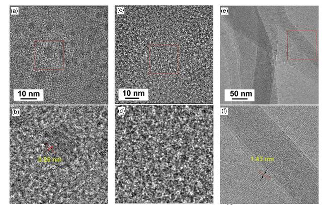
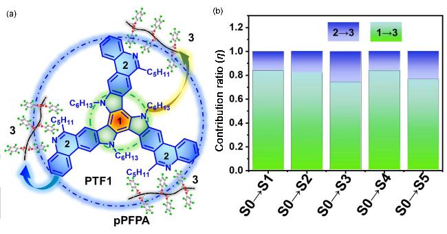
图17 (a)电子从PTF1(蓝色虚线圈段1和含有3个菲啶单位的段2)到pPFPA(段3)的跃迁示意图以及(b)不同激发态下电子贡献率Figure 17 (a) Electrons from PTF1 (blue dotted line segment 1 and contains three phenanthridine organism unit section 2) to pPFPA (segment 3) under different excited state transition diagram and (b) the electronic contribution |
3 新型刚致荧光变色分子的发射调控
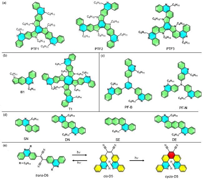
3.1 新型刚致荧光变色分子结构对发射的影响
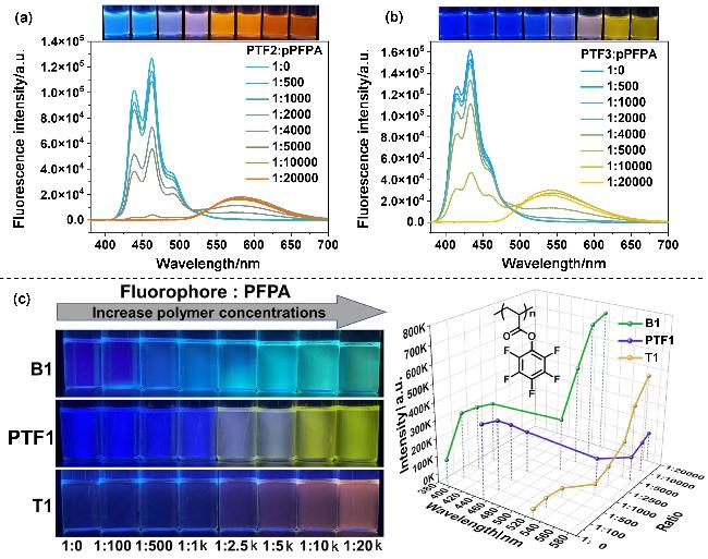
图19 (a) PTF2、 (b) PTF3随聚合物pPFPA浓度增加的发射(PFPA代表pPFPA的重复单元); (c) B1、PTF1和T1在甲苯中随pPF- PA浓度增加的荧光图像以及三种荧光团的发射波长和强度随甲苯中pPFPA浓度的增加而变化Figure 19 Emission of (a) PTF2 and (b) PTF3 with increasing concentration of polymer pPFPA (PFPA stands for repeating unit of pPFPA); (c) Fluorescence images of B1, PTF1 and T1 with increasing pPFPA concentration in toluene, and emission wavelength and intensity of the three fluorophores changed with increasing pPFPA concentration in toluene |
3.2 新型刚致荧光变色分子构象对发射的影响
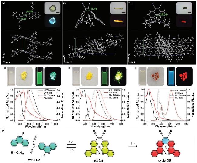
图20 (a) trans-D5、(b) cis-D5和(c) cyclo-D5的单晶结构(比例尺: 0.5 mm); (d) trans-D5、(e) cis-D5和(f) cyclo-D5在自然光和紫外光下的图像以及相应的UV-Vis和荧光发射光谱(图像的比例为1.5 cm×2 cm); (g) D5分子的化学结构和光转化Figure 20 Single crystal structures of (a) trans-D5, (b) cis-D5 and (c) cyclo-D5 (scale: 0.5 mm); Images under natural light and UV light and corresponding UV-Vis and fluorescent emission spectra of (d) trans-D5, (e) cis-D5, and (f) cyclo-D5 (the scale of the images is 1.5 cm×2 cm); (g) Chemical structures and photo transformation of D5 molecules |
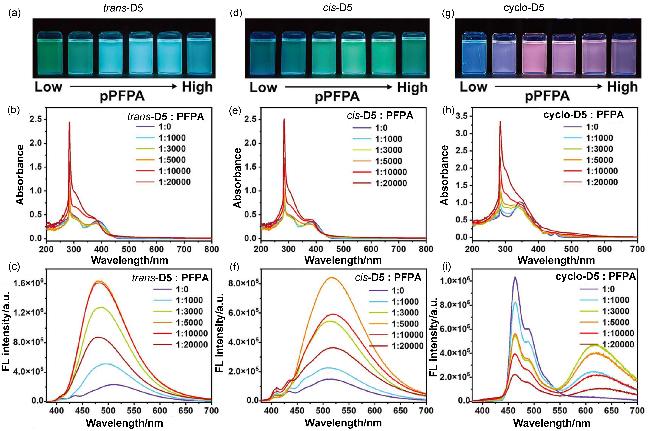
图21 (a~c) trans-D5在甲苯中的图像、紫外-可见吸收和发射光谱; (d~f) cis-D5在甲苯中的图像、紫外-可见吸收和发射光谱; (g~i) cyclo-D5在甲苯中的图像、紫外-可见吸收和发射光谱(D5浓度: 2.5×10⁻⁵ mol/L)Figure 21 (a~c) Image, UV-Vis absorption and emission spectra of trans-D5 in toluene; (d~f) Image, UV-vis absorption and emission spectra of cis-D5 in toluene; (g~i) Image, UV-vis absorption and emission spectra of cyclo-D5 in toluene (D5 concentration: 2.5×10⁻⁵ mol/L) |
3.3 聚合物分子量对新型刚致荧光变色分子发射的影响
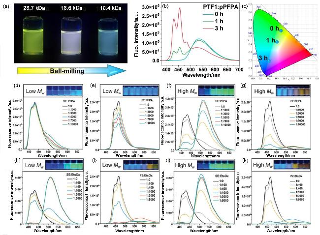
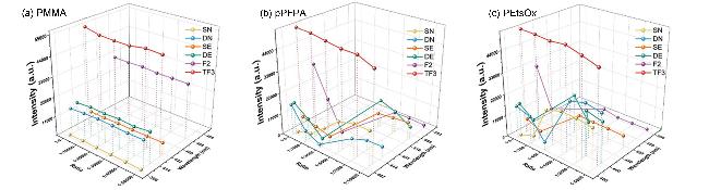
图22 PTF1/pPFPA 溶液的(a)荧光图像和(b)发射光谱; (c) PTF1/pPFPA溶液1931 CIE色度图(PTF1浓度为1.0×10⁻⁶ mol/L, pPFPA分别球磨0, 1和3 h); (d~g)不同浓度低Mw pPFPA和不同浓度高Mw pPFPA下的SE和F2的发射光谱; (h~k)不同浓度的低Mw PEtsOx和不同浓度的高Mw PEtsOx下SE和F2的发射光谱Figure 22 (a) Fluorescence image and (b) emission spectrum of PTF1/pPFPA solution; (c) 1931 CIE chromaticity diagram of PTF1/pPFPA solution (PTF1 concentration was 1.0×10⁻⁶ mol/L and pPFPA was ball-milled for 0, 1, and 3 h, respectively); (d~g) Emission spectra of SE and F2 under different concentrations of low Mw pPFPA and different concentrations of high Mw pPFPA; (h~k) Emission spectra of SE and F2 under different concentrations of low Mw PEtsOx and high Mw PEtsOx |
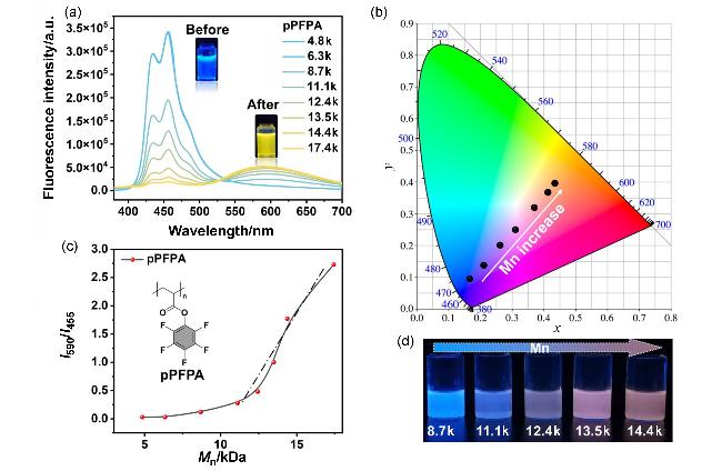
图23 (a) PTF1和PFPA单体共混物的发射光谱随溶液聚合时间的变化; (b) 1931 CIE色度坐标随pPFPA Mn的增加由蓝色变为黄色; (c) I590/I455对pPFPA Mn的曲线拟合图; (d) PTF1随pPFPA分子量变化的荧光发射图像Figure 23 (a) Emission spectra evolution of PTF1and PFPA monomer blends over the solution polymerization time; (b) 1931 CIE chromaticity coordinate changed from blue to yellow as pPFPA Mn increases; (c) Plotting I590/I455 against pPFPA Mn; (d) Fluorescence emission images of PTF1 over molecular weight variation of pPFPA |
3.4 聚合物化学结构对新型刚致荧光变色分子发射的影响
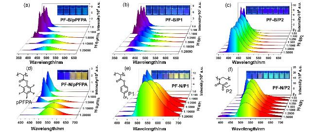
图24 pPFPA、P1和P2对PF-B (a~c)和PF-N (d~f)的荧光响应(其中的摩尔比由荧光分子和聚合物的重复单元计算, 荧光分子的浓度为2.5×10⁻⁵ mol/L)Figure 24 Fluorescence response of pPFPA, P1 and P2 to PF-B (a~c) and PF-N (d~f) (the molar ratio is calculated by the repeating unit of the fluorescent molecule and the polymer, concentration of the fluorescent molecule is 2.5×10⁻⁵ mol/L) |
3.5 聚合物拓扑结构对新型刚致荧光变色分子发射的影响
3.6 聚合物序列对新型刚致荧光变色分子发射的影响
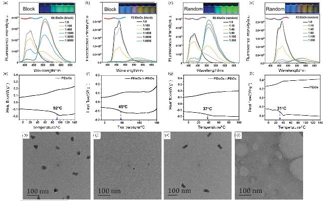
图27 (a~d)不同浓度PEtsOx-b-PEtOxSE和不同浓度PEtsOx-r-PEtOx下的SE和F2的发射光谱; (e) PEtsOx, (f) PEtsOx-b-PEtOx, (g) PEtsOx-r-PEtOx和(h) PEtOx的DSC表征; (i) SE, (j) SE/PEtsOx, (k) SE/PetsOx-b-PEtOx, (l) SE/PEtsOx-r-PEtOx共组装膜的HRTEM表征Figure 27 (a~d) Emission spectra of SE and F2 under different concentrations of PEtsOx-b-PEtOxSE and PEtsOx-r-PEtOx; DSC characterization of (e) PEtsOx, (f) PEtsOx-b-PEtOx, (g) PEtsOx-r-PEtOx, and (h) PEtOx; HRTEM characterization of (i) SE, (j) SE/PEtsOx, (k) SE/PEtsOx-b-PEtOx, and (l) SE/PEtsOx-r-PEtOx co-assembly film |
3.7 聚合物相结构对新型刚致荧光变色分子发射的影响
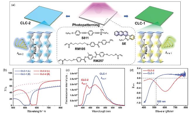
图28 (a) CLC薄膜制备工艺示意图、(b)紫外-可见CLC-1和CLC-2薄膜的透射光谱、(c) CLC-1和CLC-2薄膜的荧光发射光谱及(d) CLC-1和CLC-2薄膜的不对称因子值Figure 28 (a) Schematic diagram of CLC film preparation process, (b) UV-Vis transmission spectra of CLC-1 and CLC-2 films, (c) fluorescence emission spectra of CLC-1 and CLC-2 films, and (d) asymmetry factor values for the CLC-1 and CLC-2 films |
3.8 温度对新型刚致荧光变色分子发射的影响
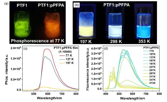
图29 (a) 纯PTF1和PTF1/pPFPA在甲苯中在77 K下的磷光图像、(b)不同温度下PTF1/pPFPA在甲苯中的荧光图像、(c) PTF1/pPFPA的磷光光谱和(d)不同温度下PTF1/pPFPA在甲苯中的发射光谱Figure 29 (a) Phosphorescence images of pure PTF1 and PTF1/pPFPA in toluene at 77 K, (b) fluorescence images of PTF1/pPFPA in toluene at different temperatures, (c) phosphorescence spectra of PTF1/pPFPA film at different temperatures, and (d) emission spectra of PTF1/pPFPA in toluene at different temperatures |
3.9 pH对新型刚致荧光变色分子发射的影响
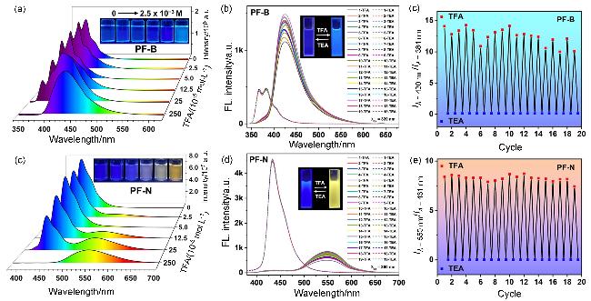
图30 不同TFA浓度甲苯中(a) PF-B和(d) PF-N的荧光光谱和图像(荧光染料的浓度为2.5×10⁻⁵ mol/L)、(b) TFA-TEA处理循环后PF-B的可逆荧光光谱变化和(c)相应的I430/I384、(e) TFA-TEA处理循环后PF-N的可逆荧光光谱变化和(f)相应的I550/I431Figure 30 Fluorescence spectra and images of (a) PF-B and (d) PF-N in toluene with different concentrations of TFA (concentration of the fluorescent dyes is 2.5×10⁻⁵ mol/L), (b) reversible fluorescence spectral change of PF-B upon cycles of TFA-TEA treatments and (c) the corresponding I430/I384, (e) reversible fluorescence spectral change of PF-N upon cycles of TFA-TEA treatments, and (f) the corresponding I550/I431 |
4 新型刚致荧光变色分子的应用
4.1 原位可视化监测聚合物的降解
4.2 基于多米诺骨牌效应的荧光传感
4.3 防伪加密技术
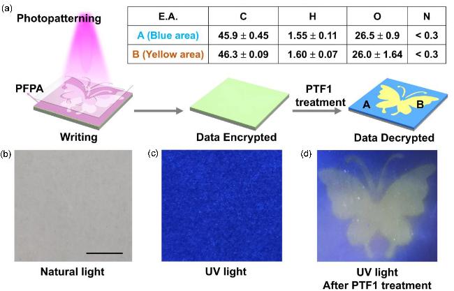
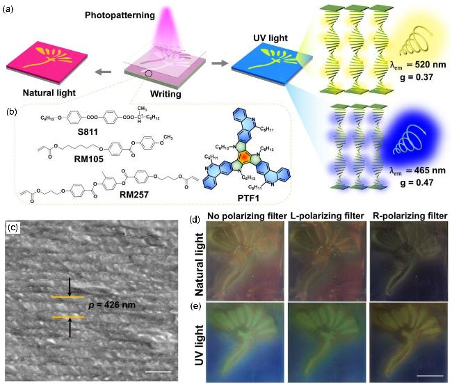
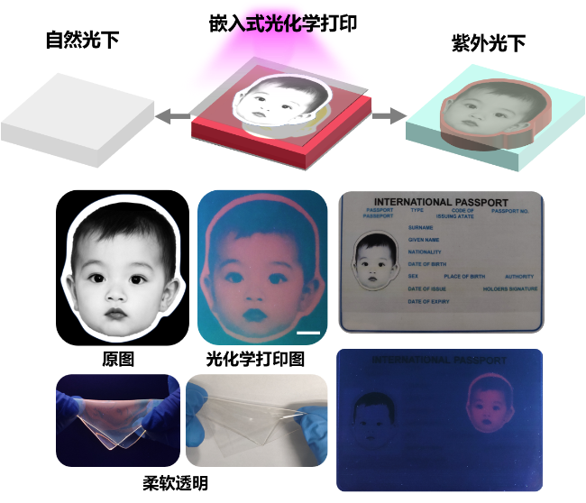
4.4 生物成像应用
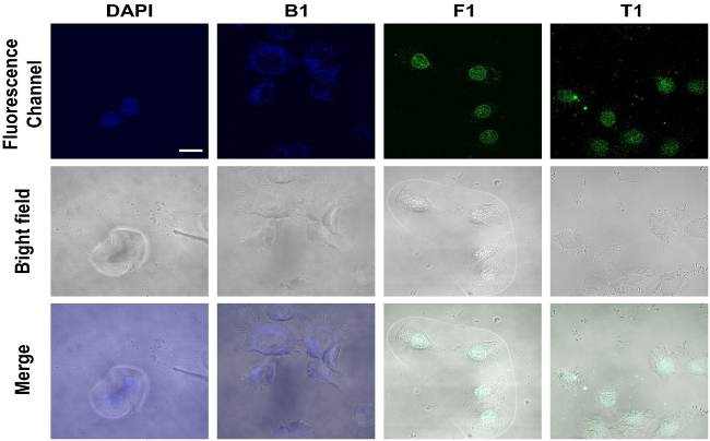


图35 使用DAPI、B1、F1和T1作为探针的活细胞成像Figure 35 Live cell imaging using DAPI, B1, F1, and T1 as the probes The excitation wavelengths (λex) for DAPI, B1, F1, and T1 are 340, 350, 360, and 360 nm, respectively. The emission wavelengths (λem) of DAPI, B1, F1, and T1 are 450, 450, 550, and 500 nm, respectively. The scale bar is 20 μm. |